Control method and device for short-circuit protection of bridge converter

A technology of short-circuit protection and control method, which is applied in the direction of emergency protection circuit device, output power conversion device, control/regulation system, etc., which can solve the problems of Vds voltage stress risk of switching tube, so as to reduce voltage stress and improve reliability Effect

Active Publication Date: 2019-11-15
SHENZHEN WINLINE TECH
View PDF2 Cites 5 Cited by
  • Summary
  • Abstract
  • Description
  • Claims
  • Application Information

AI Technical Summary

Problems solved by technology

Current symmetrical half-bridge LLC converters such as figure 1 As shown, the full-bridge LLC converter is shown as figure 2 As shown, the phase-shifted full-bridge converter as image 3 As shown, the three-level full-bridge converter is shown as Figure 4 As shown, under the traditional control strategy, when the output Vout of the bridge converter is short-circuited o...

Method used


Image

  • Control method and device for short-circuit protection of bridge converter
  • Control method and device for short-circuit protection of bridge converter
  • Control method and device for short-circuit protection of bridge converter

Examples


Embodiment 1

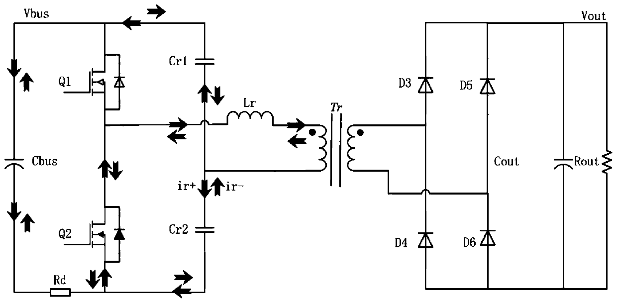
[0038] like figure 1 As shown, the main topology is a symmetrical half-bridge LLC circuit. The topology device description: Vin is the input voltage (if there is a rectifier circuit connected to the front end, it is the bus capacitor), Q1 and Q2 are N-type MOSFET switch tubes, and Cds1 is the Q1 tube Lr is the resonant inductor, Cr1 and Cr2 are the resonant capacitors, Tr is the transformer, Rd is the primary current sampling resistor, D3, D4, D5, D6 are the output diodes of the full bridge rectifier circuit, Cout is the output filter capacitor, Rout is the load, The output voltage is Vout.

[0039] When the digital control chip DSP detects a signal that the output Vout is short-circuited, the traditional control method is to turn off the drive of the upper and lower switching tubes Q1 and Q2 at the same time. At this time, the remaining energy in the resonant cavity can only pass through the junction capacitance between the resonant cavity and the switching tube. The impedan...

Embodiment 2

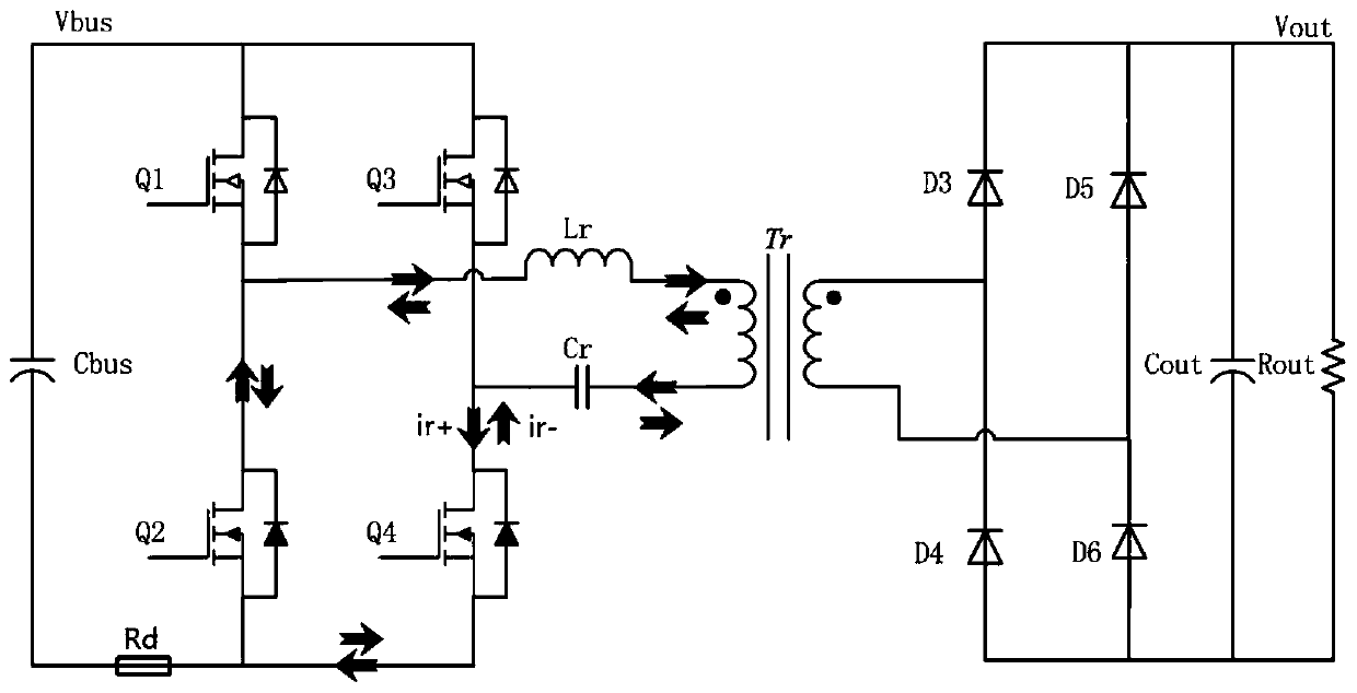
[0044] like figure 2 As shown, the main topology is a full-bridge LLC circuit. This topology device description:

[0045] like figure 2As shown, the main topology is a full-bridge LLC circuit. This topology device description: Vin is the input voltage (if the front end is connected to a rectifier circuit, it is the bus capacitor), Q1, Q2, Q3, and Q4 are N-type MOSFET switches, and Cds1 , Cds2, Cds3, and Cds4 are the junction capacitances of the drain and source of the MOS tube, Lr is the resonant inductor, Cr is the resonant capacitor, Tr is the transformer, Rd is the primary current sampling resistor, D3, D4, D5, and D6 are the full bridge The output diode of the rectifier circuit, Cout is the output filter capacitor, Rout is the load, and the output voltage is Vout.

[0046] In this embodiment, when a short circuit occurs at the output terminal, the digital control chip DSP detects a short circuit signal or an overcurrent signal on the primary side, and immediately turns...

Embodiment 3

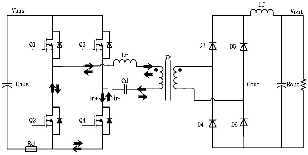
[0050] Such as image 3 As shown, the main topology is a phase-shifted full-bridge circuit, and the topology device description:

[0051] Such as image 3 As shown, the main topology is a phase-shifted full-bridge circuit. The topology device description: Vin is the input voltage (if the front end is connected to a rectifier circuit, it is the bus capacitor), Q1, Q2, Q3, and Q4 are N-type MOSFET switches. Cds1, Cds2, Cds3, and Cds4 are the junction capacitances of the drain and source of the MOS transistor, Lr is the resonant inductor, Cr is the resonant capacitor, Tr is the transformer, Rd is the primary current sampling resistor, D3, D4, D5, and D6 are all The output diode of the bridge rectifier circuit, Lf is the output filter inductor, Cout is the output filter capacitor, Rout is the load, and the output voltage is Vout.

[0052] In this embodiment, when a short circuit occurs at the output end, the digital control chip DSP detects a short circuit signal or an overcurre...


PUM


Abstract

The invention discloses a control method and device for short-circuit protection of a bridge converter. The output voltage of the bridge converter is detected; when the output of the bridge converteris detected to have a short circuit, firstly the drive of an energy transfer switch tube is controlled to be turned off, and then the drive of a freewheeling switch tube is controlled to be turned offafter the time delay [delta]t. A detection unit is used for detecting the output voltage of the bridge converter and is used for primary side bus current overcurrent protection. A control unit is used for controlling the on-off of the drive of all switch tubes in the bridge converter. By adopting a selective switch tube drive wave sealing strategy, the drive of the freewheeling switch tube is wave sealed when an output short circuit occurs, so that only a resonant inductor and a resonant capacitor oscillate in the resonant cavity, the oscillation with a parasitic capacitor in the switch tubebody is avoided, and the drive of the freewheeling switch tube is turned off when the energy in the resonant cavity is exhausted. According to the invention, the voltage stress of the switch tube during the output short circuit state and the primary side overcurrent protection of the bridge converter is reduced, and the reliability of the system is improved.

Description

technical field [0001] The present invention relates to the technical field of power electronics, and more specifically relates to a vehicle-mounted charger, a vehicle-mounted DCDC, a charging module, and a high-frequency switching power supply. Background technique [0002] Based on the high efficiency and high power density of the bridge converter, it is widely used in the fields of new energy vehicle on-board chargers, on-board DCDC, charging modules, and high-frequency switching power supplies. However, when the output of the bridge converter is short-circuited The problem of too much voltage stress of the switching tube is still one of the difficulties in the research of bridge converters. Current symmetrical half-bridge LLC converters such as figure 1 As shown, the full-bridge LLC converter is shown as figure 2 As shown, the phase-shifted full-bridge converter as image 3 As shown, the three-level full-bridge converter is shown as Figure 4 As shown, under the tra...

Claims


Application Information

Patent Timeline
IPC IPC(8): H02H7/12H02M3/335
CPCH02H7/1213H02M3/33569Y02B70/10
Inventor 张凯旋李晨光朱建国付加友陈小平
Owner SHENZHEN WINLINE TECH
Why Eureka
Try Eureka