Billet counting device and method based on machine vision technology

A machine vision and billet technology, which is applied in the field of billet counting devices, can solve the problems of measurement error, unfixed quantity, and difficulty in meeting the cost accounting requirements of steelmaking plants, so as to avoid identification errors and reduce labor intensity.

Inactive Publication Date: 2019-11-19
CHANGZHOU INST OF TECH
View PDF0 Cites 7 Cited by
  • Summary
  • Abstract
  • Description
  • Claims
  • Application Information

AI Technical Summary

Problems solved by technology

The traditional detection method is to use a ruler for manual measurement. The billet management of the continuous casting machine also adopts the method of manually measuring the count of the billet. Although it meets the detection accuracy requirements to a large extent, it requires manual operation and works in mass production. The efficiency is not high, there are certain defects and measurement errors, resulting in inaccurate billet count measurement, which is difficult to meet the cost accounting requirements of steel mills
[0004] General machine vision image acquisition devices and methods have high requirements on the environment, while the steel billet production environment is almost close to open-air production, the environment is harsh, the steel temperature varies from high to low, there are many specifications, and the quantity is not fixed, and various external interferences are very complicated. When the camera collects the image of the billet, various disturbances from the outside world will confuse the vision of the machine, and finally the contour image of the billet collected will become blurred

Method used


Image

  • Billet counting device and method based on machine vision technology
  • Billet counting device and method based on machine vision technology
  • Billet counting device and method based on machine vision technology

Examples


Embodiment Construction

[0037] In order to facilitate the understanding of those skilled in the art, the present invention will be further described below in conjunction with the embodiments and accompanying drawings.

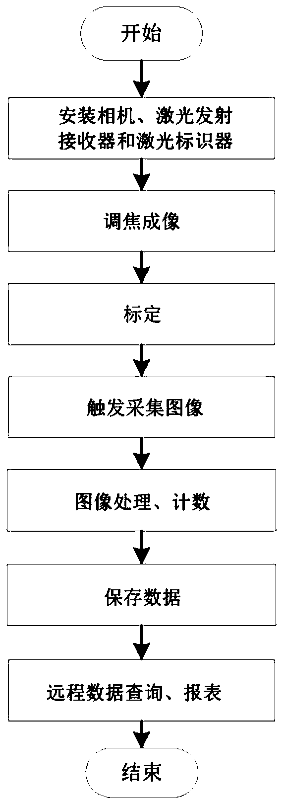
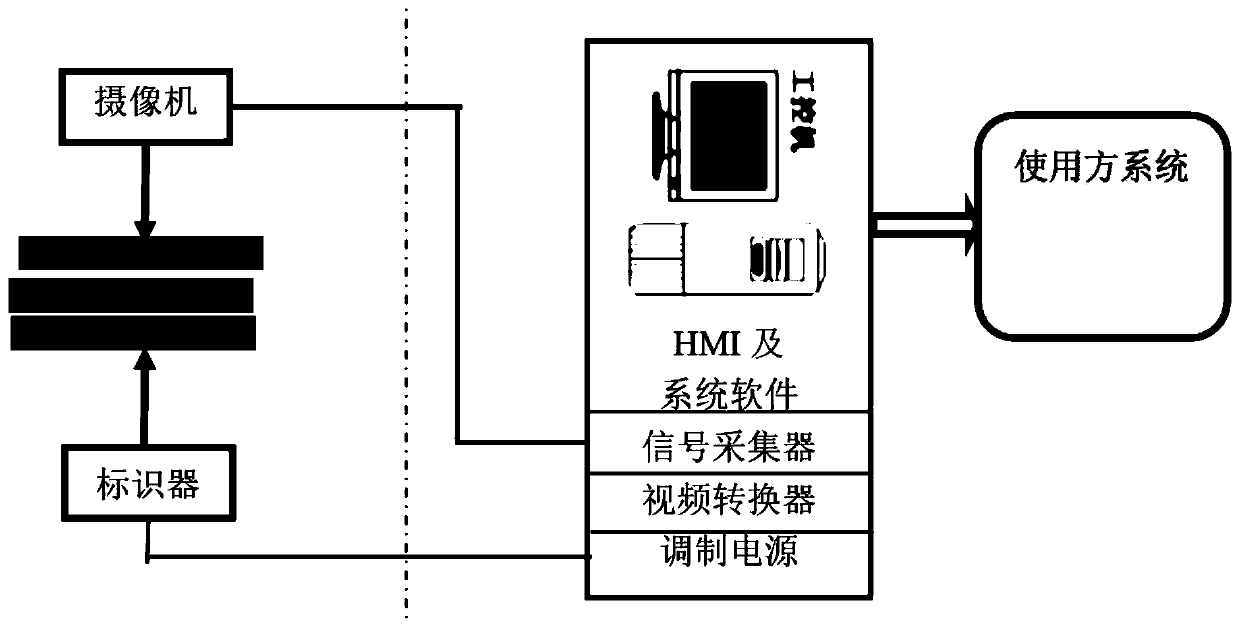
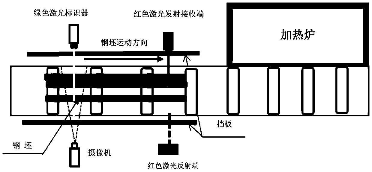
[0038] Machine vision inspection technology uses image processing to complete industrial measurement and inspection. It has the advantages of simple structure, non-contact, good flexibility, high precision, fast speed, high level of automation and intelligence, and can well meet the inspection requirements and ensure product quality. Through the application of billet counting devices and methods based on machine vision technology, together with powerful data acquisition and processing software, it can meet the requirements of accurate counting of billet counts and steelmaking cost accounting in steelmaking plants, and at the same time reduce the labor intensity of staff And the errors caused by manual calculations, so that the billets can be counted accurately. Through the automatic o...


PUM


Abstract

The invention discloses a billet counting device based on a machine vision technology. The billet counting device comprises a laser marker, a laser transceiver, a camera and a laser reflector, the laser marker and the laser transceiver are installed on one side of the conveying roller way, the camera is installed on the other side of the conveying roller way and opposite to the laser marker, and the laser reflector is installed on the other side of the conveying roller way and opposite to the laser transceiver. The laser marker obliquely irradiates the conveying roller way downwards, and the irradiation direction is perpendicular to the moving direction of the conveying roller way. The camera is additionally provided with an optical filter, and the optical filter is matched with the wavelength of the laser marker. The invention further discloses a steel billet counting method based on the machine vision technology, the width value of the steel billet is obtained based on the machine vision technology, the number of the steel billets is accurately counted, and the requirements for accurately metering the number of the steel billets and accounting the steelmaking cost of a steelmaking plant can be met.

Description

technical field [0001] The invention belongs to the field of iron and steel manufacturing, in particular to a device and method for billet counting based on machine vision technology. Background technique [0002] The measurement technology based on machine vision (Machine Vision, MV) is a technology that uses computers to process images or videos collected by machine vision products, so as to realize the perception, recognition and understanding of scenes in the objective world, and finally realize non-contact Get the data of the target object. Various research theories and research methods of machine vision have been widely used in various fields such as industrial automation production lines, various inspections and monitoring, visual navigation, automatic image interpretation, human-computer interaction and virtual reality, and have played a huge role in steel manufacturing . [0003] At present, in the production process of most iron and steel manufacturing enterprise...

Claims


Application Information

Patent Timeline
Patent Type & Authority Applications(China)
IPC IPC(8): G06M1/272G06T7/10G06T7/136G01B11/04
CPCG01B11/046G06M1/272G06T7/10G06T7/136G06T2207/20192G06T2207/30242
Inventor 唐土生徐胜德唐寅李慧
Owner CHANGZHOU INST OF TECH
Why Eureka
Try Eureka