Low-thermal-resistance and low-temperature luminescent powder layer LED

A technology of light-emitting diodes and luminescent powder, which is applied in the direction of electrical components, circuits, semiconductor devices, etc., can solve the problems of complex process, high cost, and accelerated light decay, and achieve uniform luminescent powder layer, simple manufacturing process, and simple coating process Effect

Inactive Publication Date: 2019-11-26
郑州希硕信息科技有限公司
View PDF0 Cites 0 Cited by
  • Summary
  • Abstract
  • Description
  • Claims
  • Application Information

AI Technical Summary

Problems solved by technology

At present, because about 80% of the electric energy input into the LED will be converted into heat energy, the heat mainly comes from the p-n junction of the LED chip, the temperature around the chip is very high, and the luminescent powder layer is just here. The area load power is more than 2,000 times that of ordinary fluorescent lamps, and its surface brightness is as high as 6 million cd / m 2 Above, such a high surface brightness will be detrimental to the human eye, and high temperature will lead to a decrease in the luminous efficiency of the luminescent powder, accelerated light decay, and shortened life of the LED;
[0003] Secondly, the coating uniformity of the luminescent powder of the current white light power LED is poor, the process is complicated, and the consistency is poor. This is another problem in the current manufacture of high-power white power LEDs.
[0004] In addition, the manufacturing process of white light power type LEDs is complicated, difficult to produce in large quantities, and the cost is high.

Method used


Image

  • Low-thermal-resistance and low-temperature luminescent powder layer LED
  • Low-thermal-resistance and low-temperature luminescent powder layer LED
  • Low-thermal-resistance and low-temperature luminescent powder layer LED

Examples


Embodiment Construction

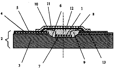
[0021] The present invention will be described in detail below in conjunction with accompanying drawing: figure 1 It is a schematic structural diagram of an embodiment of the power light emitting diode of the present invention. It includes at least one light-emitting diode chip 1, at least one metal-based circuit board 2, the metal base 3 of the circuit board 2 is a high thermal conductivity plate such as copper or aluminum, and an insulating layer 4 and a conductive layer 5 are arranged on the metal base. Chip place does not have insulating layer 4 and conductive layer 5, is a light reflection surface or light reflection bowl 6 ( figure 1 Shown is an example of a light reflection bowl), the light-emitting diode chip 1 is fixed on the metal base 3 with high thermal conductivity glue 7, the electrodes of the light-emitting diode chip are connected to the conductive layer 5 through the lead wire 8, and the conductive layer 5 is used to connect the external surface at the same ti...


PUM


Abstract

A low-thermal-resistance and low-temperature luminescent powder layer LED includes at least one LED chip and a metal substrate with high thermal conductivity, such as a metal-based circuit board. TheLED chip is mounted or flip-chip mounted on the metal substrate. The electrodes of the LED chip are led out by leads and a conductor insulated from a metal base. The light-emitting surface of the LEDchip has a light-transmitting medium layer which contains light-scattering powders. A light-transmitting cover is disposed on the light-transmitting medium layer. A luminescent powder layer is disposed on the inner surface of the light-transmitting cover. The luminescent powders have a simple coating process, are uniform, and good in consistency. The luminescent powder layer has a large area, is not directly contact with the LED chip, is low in temperature, high in light-emitting efficiency, and low in light attenuation. The LED has a long service life and a simple manufacturing process, and can be produced in large batches. The LED can be used for lighting, decorative lamps, solar lamps, mining lamps, table lamps, bedside lamps, vehicle and ship lamps and displays.

Description

technical field [0001] The invention relates to a high-power, low-thermal-resistance, low-temperature luminescent powder layer light-emitting diode, which is used for lighting, decorative lights, solar lights, miner's lamps, lighting projects and displays. Background technique [0002] In the prior art white light power type light emitting diodes, the light emitting diode chip emitting blue light or ultraviolet light is usually flipped on the silicon wafer first, and then installed on the metal base; there are luminescent powders on the light emitting surface of the chip and its surroundings, which can absorb blue light And emit yellow light, and then mix with blue light to produce white light, or absorb ultraviolet light to emit white light. At present, because about 80% of the electric energy input into the LED will be converted into heat energy, the heat mainly comes from the p-n junction of the LED chip, the temperature around the chip is very high, and the luminescent p...

Claims


Application Information

Patent Timeline
IPC IPC(8): H01L33/64H01L33/62H01L33/50H01L33/56
CPCH01L33/502H01L33/56H01L33/62H01L33/64
Inventor 普新勇赵素珍
Owner 郑州希硕信息科技有限公司
Why Eureka
Try Eureka