A denitrification system and denitrification method for high-efficiency SCR denitrification of a gas turbine unit

A technology of gas turbines and gas turbines, applied in separation methods, chemical instruments and methods, gas treatment, etc., which can solve the difficulties of ensuring the uniformity and thoroughness of mixing flue gas and ammonia gas, the difficulty of connecting heat sources and the preparation and storage of ammonia gas, It is difficult to meet the requirements of compact layout of gas turbines, etc., to achieve the effect of optimizing the mixing deviation of ammonia gas and flue gas, high mixing uniformity, and reducing working hours

Active Publication Date: 2022-03-01
SHANDONG ELECTRIC POWER ENG CONSULTING INST CORP
View PDF13 Cites 1 Cited by
  • Summary
  • Abstract
  • Description
  • Claims
  • Application Information

AI Technical Summary

Problems solved by technology

The process and equipment are complicated, the floor area is large, the heat source connection and ammonia preparation and storage are difficult, and the system piping is complex, which makes it difficult to meet the compact layout requirements of the gas turbine
The pyrolysis response of urea is too long, and the long-term operation of the pyrolysis reactor is prone to problems, which affects the denitrification efficiency of the gas turbine
In addition, it is difficult to ensure the uniformity and thoroughness of the mixing of flue gas and ammonia gas through the ammonia injection grid, and the flow field in the flue is complicated, and the contact between the catalyst and the flue gas is insufficient, which reduces the denitrification efficiency

Method used


Image

  • A denitrification system and denitrification method for high-efficiency SCR denitrification of a gas turbine unit
  • A denitrification system and denitrification method for high-efficiency SCR denitrification of a gas turbine unit
  • A denitrification system and denitrification method for high-efficiency SCR denitrification of a gas turbine unit

Examples


Embodiment Construction

[0054] It should be noted that the following detailed description is exemplary and intended to provide further explanation of the present invention. Unless defined otherwise, all technical and scientific terms used herein have the same meaning as commonly understood by one of ordinary skill in the art to which this invention belongs.

[0055] It should be noted that the terminology used here is only for describing specific embodiments, and is not intended to limit exemplary embodiments according to the present invention. As used herein, unless the context clearly dictates otherwise, the singular is intended to include the plural, and it should also be understood that when the terms "comprising" and / or "comprising" are used in this specification, they mean There are features, steps, operations, means, components and / or combinations thereof.

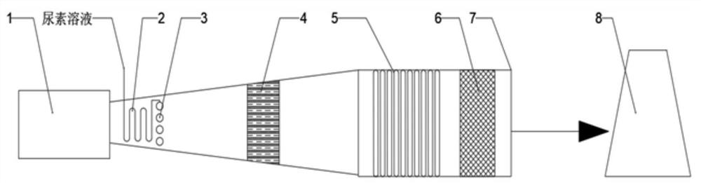
[0056] Such as figure 1 As shown, a gas turbine unit SCR denitrification system with high efficiency denitrification includes:

[0057...


PUM

PropertyMeasurementUnit
thicknessaaaaaaaaaa

Abstract

The invention discloses a gas turbine unit SCR denitrification system with high efficiency. Upstream of the gas channel, one end is used to connect with the urea solution source, and the other end is provided with a spray gun, and the injection direction of the spray gun is consistent with the axial direction of the flue gas channel; The downstream of the flue gas is used to convert the spiral motion of the flue gas into a linear motion along the flue gas channel; and the catalyst layer is arranged in the flue gas channel and is located downstream of the heat exchange tube bundle. The catalyst layer is a honeycomb structure or a corrugated plate structure . The denitration system has the advantages of high denitration efficiency, stable performance, compact layout, simple equipment, energy saving and environmental protection.

Description

technical field [0001] The invention belongs to the technical field of waste gas pollution control, and in particular relates to a denitration system and a denitration method for efficient SCR denitration of a gas turbine unit. Background technique [0002] The information disclosed in this background section is only intended to increase the understanding of the general background of the present invention, and is not necessarily taken as an acknowledgment or any form of suggestion that the information constitutes the prior art already known to those skilled in the art. [0003] With the rapid development of the world, especially Chinese society, safety, environmental protection and new energy have become the themes, and the discharge and treatment of gas, liquid and solid pollutants have reached unprecedented heights. The emission control of nitrogen oxides has also become the top priority of gas pollution control. At present, domestic Beijing, Tianjin, and Shenzhen have is...

Claims


Application Information

Patent Timeline
Patent Type & Authority Patents(China)
IPC IPC(8): B01D53/86B01D53/56
CPCB01D53/8625B01D2258/01B01D2251/2062
Inventor 张军梅刘强栾涛王志强岳建雄
Owner SHANDONG ELECTRIC POWER ENG CONSULTING INST CORP
Why Eureka
Try Eureka