A method for automatic measurement and setting of workpiece plane by machine tool probe

An automatic measurement and probe technology, applied in computer control, comprehensive factory control, program control, etc., can solve problems such as wrong clamping, parts out of tolerance and scrapped, complex shapes, etc., to improve product quality and work efficiency.

Active Publication Date: 2022-05-06
CHENGDU AIRCRAFT INDUSTRY GROUP
View PDF18 Cites 0 Cited by
  • Summary
  • Abstract
  • Description
  • Claims
  • Application Information

AI Technical Summary

Problems solved by technology

In batch processing, due to the cumbersome operation, operators often use random spot checks to check and set Z0, which may lead to undiscovered consequences of incorrect clamping of unsampled workpieces, resulting in the occurrence of out-of-tolerance scrapping of workpieces
Most of the parts in the aviation manufacturing industry are complex in shape, high in process requirements, and expensive in materials. The out-of-tolerance scrapping of parts due to operational errors has brought huge losses to the company.

Method used


Image

  • A method for automatic measurement and setting of workpiece plane by machine tool probe
  • A method for automatic measurement and setting of workpiece plane by machine tool probe
  • A method for automatic measurement and setting of workpiece plane by machine tool probe

Examples


Embodiment Construction

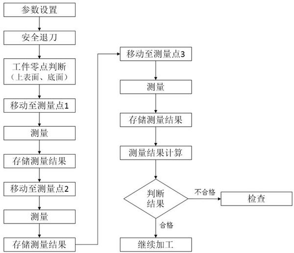
[0064] A method for automatically measuring and setting a workpiece plane by a machine tool probe, comprising the following steps:

[0065] Step 1. Selection of the basic measurement program of the numerical control system;

[0066] Step 2. Selection and distribution of measurement parameters;

[0067] Step 3: Measuring program structure design;

[0068] Step 4, measuring the parameter design of the probe motion trajectory required;

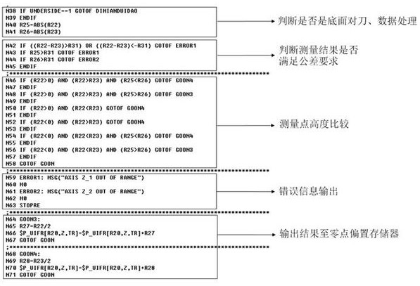
[0069] Step 5, comparison and judgment of measured values.

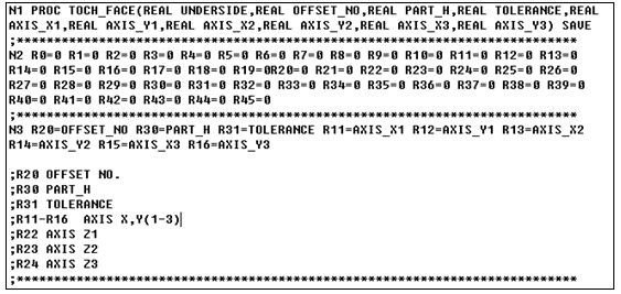
[0070] Said step one is specifically: based on the Siemens CNC system with the standard measurement cycle CYCLE978, use the Siemens system to provide the subroutine function with formal parameters, compile the automatic measurement cycle program of the nested CYCLE978 measurement subroutine, and use the subroutine as the user cycle to use.

[0071] The second step is specifically: selecting parameters for controlling the movement of the measurement point.

[0072] Specifically sele...


PUM


Abstract

This application belongs to the field of numerical control machining, and is specifically a method for automatically measuring and setting a workpiece plane by a machine tool probe, which includes the following steps: Step 1, the selection of the basic measurement program of the numerical control system; Step 2, the selection of measurement parameters and Assignment; Step 3, measurement program structure design; Step 4, parameter design of the probe motion trajectory required for measurement; Step 5, comparison and judgment of measured values. This application optimizes the programming based on the measurement operations required in actual processing. This method simplifies the complicated and cumbersome G code programming by parametrically inputting the trajectory programming required for measurement. Bring convenience, improve product quality and work efficiency.

Description

technical field [0001] The application belongs to the field of numerical control machining, and specifically relates to a method for automatically measuring and setting workpiece planes by a machine tool probe. Background technique [0002] Machining technology generally follows the "positioning-processing" operation mode. According to this mode, how to realize the precise positioning of the processed workpiece according to the design and process requirements has become a primary issue to ensure the qualified processing of the workpiece. The alignment and setting of the Z0 plane in NC machining is a necessary process of NC machining. The traditional alignment method is that the operator uses a standard tool setting block to set the tool on the machine tool to find the position of the Z0 plane reference, and then use the calculation function of the machine tool or Manually input relevant data into the numerical control system to set the coordinate system of the workpiece. Thi...

Claims


Application Information

Patent Timeline
Patent Type & Authority Patents(China)
IPC IPC(8): G05B19/401
CPCG05B19/4015G05B2219/37068Y02P90/02
Inventor 周良明康志文李维亮贺珣曹克江
Owner CHENGDU AIRCRAFT INDUSTRY GROUP
Why Eureka
Try Eureka