Limiting structure for intelligent printing machine

A limit structure, technology of printing presses, applied in printing presses, general parts of printing machinery, printing and other directions, can solve problems such as difficulty in meeting demand, general positioning effect of substrates, etc., to achieve good integrity, not easy to shift, and stable. Good results

Active Publication Date: 2019-12-17
杭州敏邦实业有限公司
View PDF13 Cites 0 Cited by
  • Summary
  • Abstract
  • Description
  • Claims
  • Application Information

AI Technical Summary

Problems solved by technology

[0003] The positioning effect of the current printing machine on the su

Method used


Image

  • Limiting structure for intelligent printing machine
  • Limiting structure for intelligent printing machine
  • Limiting structure for intelligent printing machine

Examples


Example Embodiment

[0043] Example 1

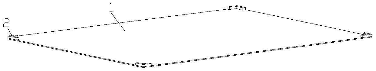
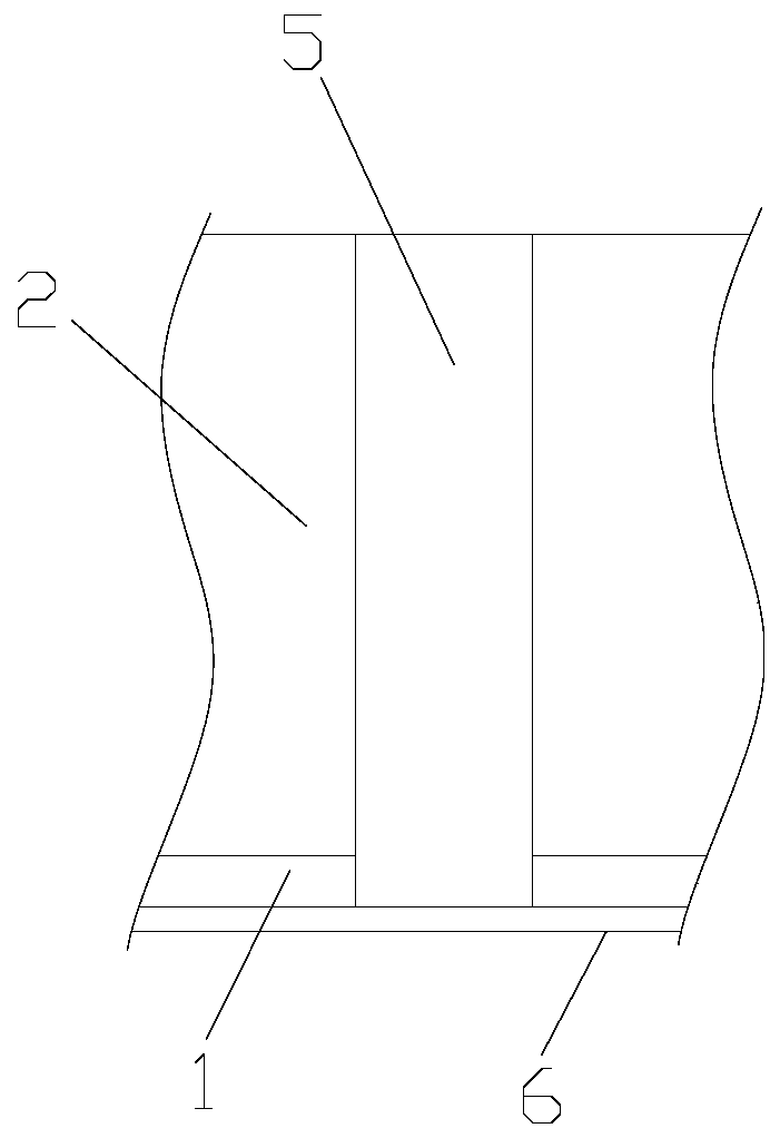
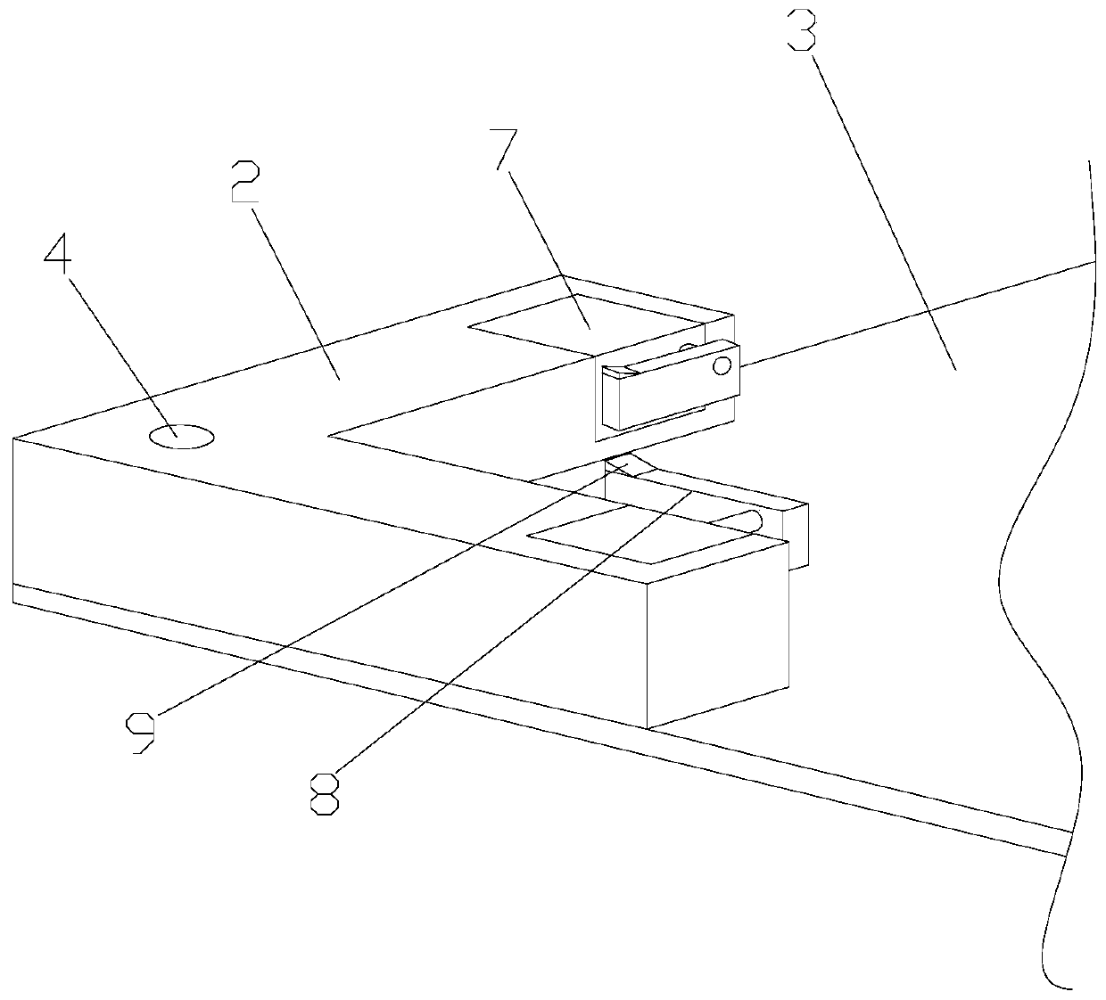
[0044] Such as Figure 1-4 As shown, a limit structure for a smart printer includes an electrostatic adsorption film 1 for installation on a conveyor belt. Four corners of the electrostatic adsorption film 1 are provided with limit blocks 2, and the limit The position block 2 is arranged in an L shape, the limit block 2 is fixedly connected to the electrostatic adsorption film 1, and both ends of the limit block 2 are provided with clamping devices for clamping the substrate. The electrostatic adsorption film 1 And the limit block 2 constitute a placement groove 3 that fits the substrate, and the electrostatic adsorption film is composed of 130 parts of polyvinyl chloride resin, 45 parts of polytetrafluoroethylene, and dioctyl phthalate in a proportion by weight. 2 parts, 7 parts of ethyl cellulose, 3 parts of epoxy soybean oil, 5 parts of barium titanate, 1 part of 2-hydroxypropyl acrylate, 6 parts of hydrotalcite, 5 parts of paraffin, 1 part of dibutyl tin d...

Example Embodiment

[0055] Example 2

[0056] Such as Figure 1-4 As shown, a limit structure for a smart printer includes an electrostatic adsorption film 1 for installation on a conveyor belt. Four corners of the electrostatic adsorption film 1 are provided with limit blocks 2, and the limit The position block 2 is arranged in an L shape, the limit block 2 is fixedly connected to the electrostatic adsorption film 1, and both ends of the limit block 2 are provided with clamping devices for clamping the substrate. The electrostatic adsorption film 1 And the limit block 2 constitute a placement groove 3 that fits the substrate, and the electrostatic adsorption film is composed of 150 parts by weight of polyvinyl chloride resin, 65 parts of polytetrafluoroethylene, and dioctyl phthalate. 4 parts, 10 parts of ethyl cellulose, 5 parts of epoxidized soybean oil, 7 parts of barium titanate, 3 parts of 2-hydroxypropyl acrylate, 8 parts of hydrotalcite, 7 parts of paraffin, 3 parts of dibutyl tin dilaurate...


PUM


Abstract

The invention discloses a limiting structure for an intelligent printing machine. The structure comprises an electrostatic adsorption film arranged on a conveyor belt, limiting blocks are arranged atthe four corners of the electrostatic adsorption film, the limiting blocks are arranged in an L-shaped mode, the limiting blocks are fixedly connected with the electrostatic adsorption film, the two ends of the limiting blocks are provided with clamping devices used for clamping a printed material, the electrostatic adsorption film and the limiting blocks form a placing groove matched with the printed material, and the electrostatic adsorption film is prepared by the following components of, in parts by weight, 130-150 parts of polyvinyl chloride resin, 45-65 parts of polytetrafluoroethylene,2-4 parts of dioctyl phthalate, 7-10 parts of ethyl cellulose, 3-5 parts of epoxidized soybean oil, 5-7 parts of barium titanate, 1-3 parts of acrylic acid-2-hydroxypropyl acrylate, 6-8 parts of hydrotalcite, 5-7 parts of paraffin, 1-3 parts of dibutyltin dilaurate, 1-3 parts of tetrabutyl tin, 7-11 parts of nano neodymium oxide and 3-8 parts of fluoroalkyl polyether modified polysiloxane. According to the limiting structure for the intelligent printing machine, the printed material can be well limited and positioned.

Description

Technical field [0001] The invention relates to a limit structure for an intelligent printing machine. Background technique [0002] Machines that print text and images. Modern printing presses are generally composed of plate loading, inking, embossing, and paper feeding mechanisms. Its working principle is: first make the text and image to be printed into a printing plate, install it on the printing machine, and then apply ink to the place where there are text and image on the printing plate by manual or printing machine, and then directly or indirectly transfer it. Print on paper or other substrates to reproduce the same print as the printing plate. The invention and development of the printing press play an important role in the spread of human civilization and culture. [0003] The current printing press has a general positioning effect on the substrate, which is difficult to meet the market demand. Summary of the invention [0004] The technical problem to be solved by the ...

Claims


Application Information

Patent Timeline
IPC IPC(8): B41F21/00C08L27/06C08L27/18C08L1/28C08L91/00C08L91/06C08L83/12C08K13/02C08K5/12C08K3/26C08K3/22C08K5/57C08J5/18
CPCB41F21/00C08J5/18C08J2327/06C08J2401/28C08J2427/18C08J2483/12C08J2491/00C08J2491/06C08K3/26C08K5/12C08K5/57C08K13/02C08K2003/221C08K2201/011
Inventor 不公告发明人
Owner 杭州敏邦实业有限公司
Why Eureka
Try Eureka