Heat treatment quenching agent
A technology of quenching agent and initiator, which is applied in the direction of quenching agent, heat treatment equipment, manufacturing tools, etc., can solve the problem of loss of odor of quenching agent, and achieve the effect of avoiding temperature rise and odor
- Summary
- Abstract
- Description
- Claims
- Application Information
AI Technical Summary
Problems solved by technology
Method used
Image

Examples
Embodiment 1
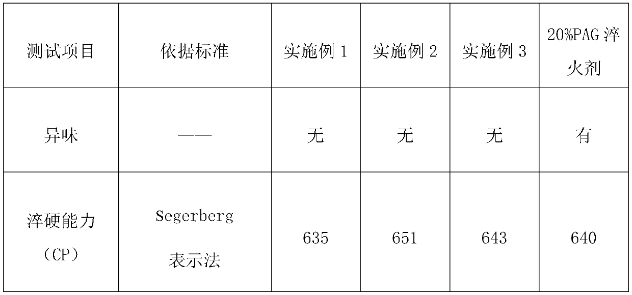
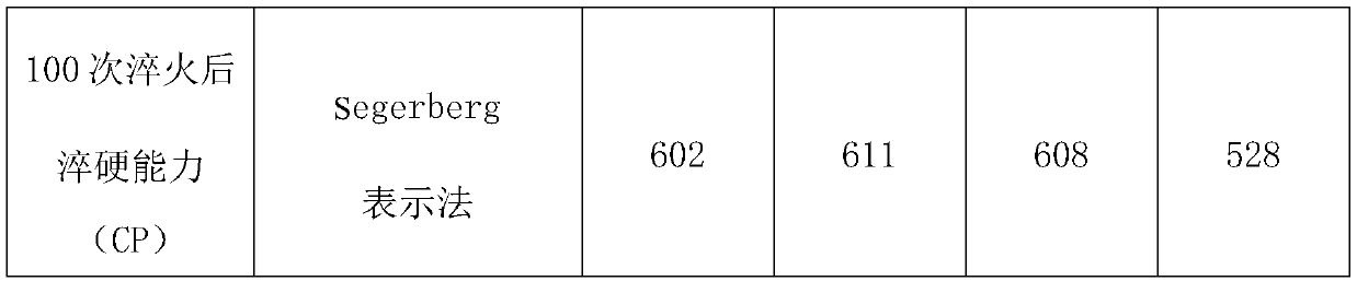
[0027] A quenching agent for heat treatment consists of the following components in parts by weight: 30 parts of sodium silicate, 5 parts of sodium hydroxide, 7 parts of phase-change energy storage microcapsules, and 40 parts of water.
[0028] The phase-change energy storage microcapsules are prepared by the following method: mix graphite and DMF at a weight ratio of 1:20, stir at a high speed at 2000 rpm until the mixed solution is uniform without sediment, add n-octadecane to maintain the original speed and continue Stir until uniform, the amount of n-octadecane added is 3-4 times the weight of graphite; add polycaprolactone polyol, stir evenly and heat to 50-55°C, add isophorone diisocyanate and dilauric acid diisocyanate in proportion The butyl tin was reacted for 1 hour; titanium dioxide was added, stirred and lowered to room temperature; freeze-dried to obtain phase-change energy storage microcapsules.
[0029] The graphite is 2 microns.
[0030] The polycaprolactone p...
Embodiment 2
[0034] A quenching agent for heat treatment consists of the following components in parts by weight: 38 parts of sodium silicate, 10 parts of sodium hydroxide, 12 parts of phase change energy storage microcapsules, and 58 parts of water.
[0035] The phase change energy storage microcapsules are prepared by the following method: mix graphite and DMF at a weight ratio of 1:20, stir at a high speed of 2500 rpm until the mixed solution is uniform without sediment, add n-octadecane to maintain the original speed and continue Stir until uniform, the amount of n-octadecane added is 3-4 times the weight of graphite; add polycaprolactone polyol, stir evenly and heat to 50-55°C, add isophorone diisocyanate and dilauric acid diisocyanate in proportion The butyl tin was reacted for 2 hours; titanium dioxide was added, stirred and lowered to room temperature; freeze-dried to obtain phase-change energy storage microcapsules.
[0036] The graphite is 4 microns.
[0037] The polycaprolacton...
Embodiment 3
[0041] A quenching agent for heat treatment consists of the following components in parts by weight: 35 parts of sodium silicate, 8 parts of sodium hydroxide, 10 parts of phase change energy storage microcapsules, and 47 parts of water.
[0042] The phase-change energy storage microcapsules are prepared by the following method: mix graphite and DMF at a weight ratio of 1:20, stir at a high speed of 2200 rpm until the mixed solution is uniform without sediment, add n-octadecane to maintain the original speed and continue Stir until uniform, the amount of n-octadecane added is 3.4 times the weight of graphite; add polycaprolactone polyol, stir evenly and heat to 50-55°C, add isophorone diisocyanate and dibutyltin dilaurate in proportion to react 1.5 hours; adding titanium dioxide, stirring and cooling down to room temperature; freeze-drying to obtain phase change energy storage microcapsules.
[0043] The graphite is 3 microns.
[0044] The polycaprolactone polyol has a hydroxy...
PUM
| Property | Measurement | Unit |
|---|---|---|
| Particle size | aaaaa | aaaaa |
| Particle size | aaaaa | aaaaa |
| Particle size | aaaaa | aaaaa |
Abstract
Description
Claims
Application Information
 - Generate Ideas
- Intellectual Property
- Life Sciences
- Materials
- Tech Scout
- Unparalleled Data Quality
- Higher Quality Content
- 60% Fewer Hallucinations
Browse by: Latest US Patents, China's latest patents, Technical Efficacy Thesaurus, Application Domain, Technology Topic, Popular Technical Reports.
© 2025 PatSnap. All rights reserved.Legal|Privacy policy|Modern Slavery Act Transparency Statement|Sitemap|About US| Contact US: help@patsnap.com