

Parameter coupling design method for liquefied air energy storage system
An energy storage system and coupling design technology, applied in liquefaction, refrigeration, liquefaction, calculation, etc., can solve the problems of numerous working parameters, complex single equipment, failure to consider the interaction of the system, etc., and achieve the effect of efficient operation
- Summary
- Abstract
- Description
- Claims
- Application Information
AI Technical Summary
Problems solved by technology
Method used
Image

Examples
Embodiment 1
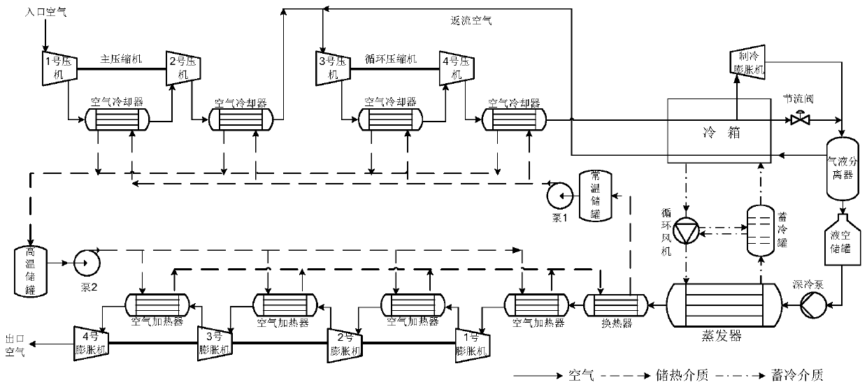
[0051] figure 2 It is a schematic diagram of a single-stage heat storage liquefied air energy storage system according to a specific embodiment of the present invention. As shown in the figure: the system includes a main compressor, a circulating compressor, a cold box, a throttle valve, a refrigeration expander, a gas-liquid separator, a liquid-air storage tank, a cryogenic pump, an evaporator, an expansion unit, and a heat storage unit And the cold storage unit, in which the main compressor is composed of No. 1 compressor and No. 2 compressor, the circulation compressor is composed of No. 3 compressor and No. 4 compressor, the expansion unit is composed of No. 1-4 expander, and the heat storage unit It is composed of normal temperature storage tank, pump 1, high temperature storage tank, pump 2, heat exchanger, 4 air coolers and 4 air heaters. The cold storage unit is composed of a circulating fan and a cold storage tank. Its working process is as follows:
[0052] When s...
Embodiment 2
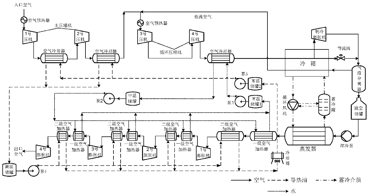
[0077] image 3It is a schematic diagram of a liquefied air energy storage system using hierarchical heat storage according to a specific embodiment of the present invention. Compared with Embodiment 1, the improvement is: the inlet of the main compressor / circulation compressor is equipped with an air preheater, and the circulation compressor It is a two-stage compression and two-stage cooling scheme; the heat storage unit adopts a two-stage heat storage scheme, which includes a medium temperature storage tank, a high temperature storage tank, a cooling tower, a normal temperature storage tank 1 and a normal temperature storage tank 2, a high temperature storage tank and a medium temperature storage tank The tank uses heat transfer oil and water as working medium respectively. When storing energy, the inlet air of the main compressor and the circulation compressor needs to be heated by the air preheater first, and then enter the main compressor and the circulation compressor f...
PUM
 Abstract
Description
Claims
Application Information