Electro-optical nutation coupling system and method for space laser communication

A laser communication and coupling system technology, applied in the field of laser communication, can solve problems such as poor system compatibility, difficulty in applying space-borne laser communication terminals, short service life, etc., and achieve strong ability to suppress platform vibration, good space environment adaptability, and use long life effect

Active Publication Date: 2019-12-20
BEIJING RES INST OF TELEMETRY +1
View PDF14 Cites 1 Cited by
  • Summary
  • Abstract
  • Description
  • Claims
  • Application Information

AI Technical Summary

Problems solved by technology

Although the above two technical solutions have realized the nutation coupling of space light to single-mode fiber in space laser communication, they have not completely solved the problem of high bandwidth, long life, compatibility with incoherent communication system and coherent communication system, and simultaneous Applied to spaceborne, airborne and ground laser communication terminals and other issues
This is because although the Chinese patent with the publication number CN104811244A uses the fast mirror nutation to realize the laser nutation coupling under the incoherent detection system, its vibration frequency is 10kHz, but the effective bandwidth of the fast mirror is less than 1kHz, usually at 500Hz Left and right, compared with the satellite platform's vibration frequency of 250Hz, the ability of the fast mirror to suppress the vibration of the satellite platform is very poor, and it is difficult to apply to the spaceborne laser communication terminal; at the same time, because the vibration of the nutating fast mirror is mechanical vibration, its service life It is related to the vibration frequency and the number of vibrations, so the service life of the fast mirror is short. At this time, it is suitable for the ground laser communication receiving system, and it is only used in the non-coherent detection system. The system compatibility is poor and the service life is short
Although the Chinese patent with the publication number CN109560878A uses optical fiber nutation to realize laser nutation coupling under the coherent detection system, the nutation is carried out by driving the piezoelectric ceramic tube clamping the single-mode optical fiber in the center. This nutation method also has mechanical problems. Movement, short service life; at the same time, this technical solution is limited to supporting coherent communication systems, and the system compatibility is poor
Due to the introduction of the mechanical movement of the optical fiber, the system has high complexity and poor stability

Method used


Image

  • Electro-optical nutation coupling system and method for space laser communication

Examples


Embodiment 1

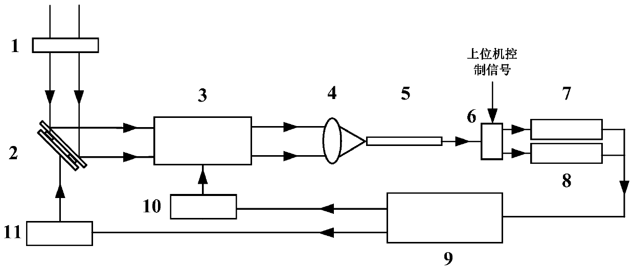
[0039] In Example 1, a beam of modulation system is OOK, a circularly polarized parallel light beam with a wavelength of 1550 nm and a diameter of about 4 mm passes through a quarter-wave plate 1 and then becomes a horizontally polarized light beam, passing through a fast reflector placed at 45° 2 enters the electro-optic deflector 3 after reflection, and the electro-optic deflector driving module 10 drives the electro-optic deflector 3 according to the control signal input by the communication and angle error solving module 9 to make the beam scan circularly, and the circular scanning beam is focused by the coupling lens 4 to The fiber end face of the single-mode fiber 5 located at the focal point of the coupling lens. At this time, due to the influence of ground vibration and atmospheric turbulence, etc., the nutation circle has shifted from the center of the fiber end face to a certain position on the end face, but the laser will still scan circularly. The signal light coup...

Embodiment 2

[0051] In Example 2, a beam of modulation system is BPSK, a circularly polarized parallel light beam with a wavelength of 1550 nm and a diameter of about 8 mm passes through a quarter-wave plate 1 and then becomes a horizontally polarized light beam, passing through a fast reflector placed at 45° 2 enters the electro-optic deflector 3 after reflection, and the electro-optic deflector driving module 10 drives the electro-optic deflector 3 according to the control signal input by the communication and angle error solving module 9 to make the beam scan circularly, and the circular scanning beam is focused by the coupling lens 4 to The fiber end face of the single-mode fiber 5 located at the focal point of the coupling lens. At this time, due to the influence of ground vibration and atmospheric turbulence, etc., the nutation circle has shifted from the center of the fiber end face to a certain position on the end face, but the laser will still scan circularly. The signal light cou...


PUM


Abstract

The invention discloses an electro-optical nutation coupling system and method for space laser communication, and belongs to the field of laser communication. The system comprises a quarter-wave plate, a fast reflector, an electro-optical deflector, a coupling lens, a single-mode optical fiber, an optical switch, an incoherent receiving module, a coherent receiving module, a communication and angle error resolving module, an electro-optical deflector driving module and a fast reflector driving module. According to the invention, based on an electro-optic deflection effect, a non-mechanical electro-optical deflection device is adopted; two-dimensional scanning and nutation coupling of a laser beam are realized by controlling the electro-optical deflector; while communication information isdemodulated, extraction of tracking angle error amount of a laser signal and calculation of compensation amount are completed, and the electro-optical deflector and the rapid reflector are controlledto perform fine tracking compensation, so that high-precision tracking of the laser signal and stable and efficient coupling from spatial light to a single-mode optical fiber are realized. The methodcan be compatible with tracking angle error calculation and compensation under incoherent and coherent communication systems.

Description

technical field [0001] The invention relates to an electro-optic nutation coupling system and method for space laser communication, belonging to the field of laser communication. Background technique [0002] Compared with traditional microwave communication, space laser communication has the characteristics of high transmission rate, strong anti-interference ability, small terminal size, low power consumption, and light weight, so it has become the most potential development direction of high-speed communication technology between satellites and satellites. one. As the demand for space laser communication networking applications becomes more and more urgent, space laser communication terminals need to be compatible with both coherent and non-coherent communication systems. Based on the advantages of fiber optic photodetection devices, at the receiving end of the space laser communication link, the space beam received by the optical system needs to be coupled into a single-...

Claims


Application Information

Patent Timeline
Patent Type & Authority Applications(China)
IPC IPC(8): H04B10/11H04B10/60
CPCH04B10/11H04B10/60
Inventor 赵卓刘向南向程勇廖为桂李晓亮谌明于勇李凉海
Owner BEIJING RES INST OF TELEMETRY
Why Eureka
Try Eureka