Supercharge Your Innovation With Domain-Expert AI Agents!

Spectrum calibration structure based on gradual changing optical microcavity, and preparation method

An optical microcavity, spectral calibration technology, applied in spectrometry/spectrophotometry/monochromator, optical radiation measurement, radiation pyrometry, etc., can solve problems such as offset, achieve good stability, Good applicability and improved portability

Pending Publication Date: 2019-12-24
58TH RES INST OF CETC
View PDF0 Cites 0 Cited by
  • Summary
  • Abstract
  • Description
  • Claims
  • Application Information

AI Technical Summary

Problems solved by technology

[0004] The purpose of the present invention is to provide a spectral calibration structure and preparation method based on a gradient optical microcavity to solve the problem that the read wavelength and the actual wavelength have a certain offset due to wear and tear of the traditional spectrometer

Method used


Image

  • Spectrum calibration structure based on gradual changing optical microcavity, and preparation method
  • Spectrum calibration structure based on gradual changing optical microcavity, and preparation method
  • Spectrum calibration structure based on gradual changing optical microcavity, and preparation method

Examples


Embodiment 1

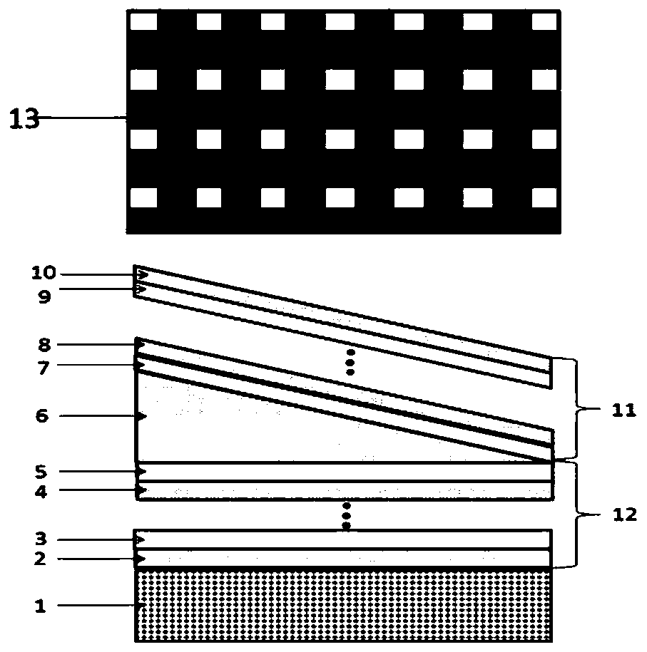
[0038] The invention provides a spectral calibration structure based on a graded optical microcavity, such as figure 1 As shown, it includes a substrate 1, on which a lower DBR 12, an intermediate cavity layer 6, an upper DBR 11 and a top unit 13 are sequentially arranged; wherein, the DBR is a Distributed Bragg Reflector, a distributed Bragg reflector. Simply irradiating monochromatic light sources on different units can quickly and accurately obtain smooth and accurate spectral curves, thereby determining the spectral wavelength position and spectral stability, and correcting wavelength shift. According to different design requirements, the narrow-band peak position at any wavelength can be obtained.

[0039] Specifically, both the lower DBR 12 and the upper DBR 11 include several high-refractive-index materials and low-refractive-index materials alternately arranged, such as figure 1 As shown, that is, the lower layer DBR 12 includes high refractive index material 2 and lo...

Embodiment 2

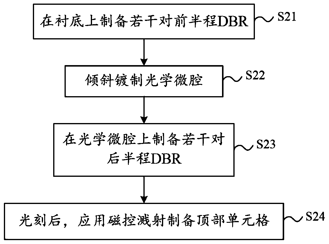
[0047] The invention provides a method for preparing a spectral calibration structure based on a graded optical microcavity, and the flow chart is as follows figure 2 shown, including:

[0048] Step S21, preparing several pairs of first-half DBRs on the substrate;

[0049] Step S22, obliquely plating the optical microcavity;

[0050] Step S23, preparing several pairs of second-half DBRs on the optical microcavity;

[0051] Step S24 , after photolithography, the top cells are prepared by magnetron sputtering.

[0052] (1) The spectral calibration structure of the spectral peak at 615nm-650nm gradient optical microcavity

[0053] According to the embodiment of the present invention, the spectral calibration structure design and structure of the spectral peak at 615nm-650nm gradient optical microcavity include the following steps:

[0054] The first step: through the Leybold visible optical coating machine, with K9 glass as the substrate, Ta 2 o 5 , SiO 2 Prepare 8 pairs ...


PUM


Abstract

The invention discloses a spectrum calibration structure based on a gradual changing optical microcavity, and a preparation method, and belongs to the technical field of optical testing. The spectrumcalibration structure based on the gradual changing optical microcavity comprises a substrate, and a lower layer DBR, a middle cavity layer, an upper layer DBR and a top unit are arranged on the substrate in sequence. A smooth and accurate spectrum curve can be obtained quickly and accurately just by irradiating different units with a monochromatic light source, so as to determine a spectral wavelength position and spectral stability and to correct the wavelength offset. Compared with the traditional method, the spectrum calibration structure disclosed by the invention has the advantages of significantly improving the portability, and the spectrum calibration structure can be widely used in high-throughput identification of light sources, food safety testing, wavelength calibration in a spectrograph calibration process, and other related applications.

Description

technical field [0001] The invention relates to the technical field of optical testing, in particular to a spectral calibration structure and a preparation method based on a gradient optical microcavity. Background technique [0002] Spectroscopy is widely used in scientific research fields such as environmental monitoring, biomedicine, remote sensing and space exploration. In the 17th century, Newton proved that prisms can decompose white light into different component colors and recombine them to produce white light; in the early 18th century, Jospehvon Fraunhofer used diffraction gratings instead of prisms as spectroscopic devices, and made great progress. The use of diffraction gratings increases the spectral resolution of the prism and quantifies the dispersed wavelengths, making spectroscopy a more refined and quantitative scientific technique. Since the advent of the Michelson interferometer, the Fourier transform spectrometer has become a very useful research tool b...

Claims


Application Information

Patent Timeline
IPC IPC(8): G01J3/02G01J3/28
CPCG01J3/0205G01J3/0259G01J3/0297G01J3/2803
Inventor 颜炎洪李杨徐衡李守委朱家昌高娜燕
Owner 58TH RES INST OF CETC
Features
  • R&D
  • Intellectual Property
  • Life Sciences
  • Materials
  • Tech Scout
  • Unparalleled Data Quality
  • Higher Quality Content
  • 60% Fewer Hallucinations
Learn More