Laser scanning method for coaxially feeding powder

A laser scanning and coaxial powder feeding technology, applied in the field of additive manufacturing, can solve the problems of insufficient partition dispersion and energy concentration, avoid heat and stress concentration, prevent heat and stress concentration, and reduce the probability of component deformation and cracking Effect

Active Publication Date: 2019-12-31
TSC LASER TECH DEV BEIJING CO LTD
View PDF9 Cites 2 Cited by
  • Summary
  • Abstract
  • Description
  • Claims
  • Application Information

AI Technical Summary

Problems solved by technology

[0005] In order to solve the problem of insufficient dispersion of partitions and too concentrated ene

Method used


Image

  • Laser scanning method for coaxially feeding powder
  • Laser scanning method for coaxially feeding powder
  • Laser scanning method for coaxially feeding powder

Examples


Embodiment 1

[0072] A laser scanning method for coaxial powder feeding, comprising the following steps:

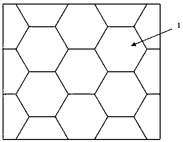
[0073] S1. Obtain and identify the contour file of the cross-section of the workpiece to be processed layer by layer. In the area of ​​the contour file of each layer, the same regular hexagon is evenly arranged to partition; the diameter of the inscribed circle of the regular hexagon is 36mm.

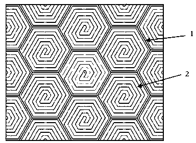
[0074] S2. Planning a scan path 2 in each of the partitions, and then deleting a partition line of the partition; the scan path 2 is composed of a forward scan path and a backfill scan path. Such as Figure 5 shown.

[0075] Planning a first polygon within said polygon 1 for partitioning, said first polygon being the same as said polygon for partitioning; planning a second polygon within said polygon 1 for partitioning ;

[0076] The forward scanning path is: starting from the end point A of the first polygon, scanning clockwise in a regular hexagonal shape with centripetal equidistant helica...

Embodiment 2

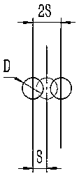
[0085] A laser scanning method for coaxial powder feeding in this embodiment is basically the same as Embodiment 1, the only difference is that the scanning distance is 3mm, the scanning step is 6mm, the width of the melting channel is 4.3mm, and the overlap ratio 30%; the diameter of the inscribed circle of the regular hexagon used for partitioning is 30mm, the diameter of the inscribed circle of the first polygon is 24mm, and the diameter of the inscribed circle of the second polygon is 3mm; the laser scanning is performed first A laser scan within the partition is performed after the bounding box scan.

[0086] Observation of the metal component of this embodiment shows that the surface is smooth, with little deformation and no cracks.

Embodiment 3

[0088] A laser scanning method for coaxial powder feeding in this embodiment is basically the same as in Embodiment 1, except that the scanning distance is 9mm, the scanning step is 18mm, the width of the melting channel is 15mm, and the overlap rate 40%; the diameter of the inscribed circle of the regular hexagon used for partitioning is 90mm, the diameter of the inscribed circle of the first polygon is 72mm, and the diameter of the inscribed circle of the second polygon is 9mm;

[0089] The forward scanning path is as follows: starting from a point on the second polygon, spirally scanning outwards equidistantly in the shape of a regular hexagon counterclockwise, and ending at endpoint A on the first polygon.

[0090] The backfill scanning path is as follows: start from point B that is flush with the end point A, scan clockwise in the shape of a regular hexagon with a centripetal equidistant spiral, and backfill until it connects with the starting point of the forward scanning...


PUM


Abstract

The invention relates to the technical field of additive manufacturing, and discloses a laser scanning method for coaxially feeding powder. The laser scanning method comprises the steps of obtaining layout files of sections of a to-be-processed workpiece layer by layer and identifying the layout files, in the area of each layer of layout file, conducting zoning in the form that a same kind of polygons is uniformly arranged, planning a scanning path in each zone, and then deleting zoning lines of the zones; conducting laser scanning on each zone in a negative lapping way by using an internallynon-overlapped isometric spiral scanning path; conducting border scanning on each layer of layout file. After zoning, heat is dispersed, energy is prevented from being too concentrated, and the deformation and cracking probability of a component is reduced. By using the isometric spiral scanning path, the problems are solved that in the prior art, reciprocating backfilling scanning is conducted inthe same layer, short edges are mutually overlapped, and the flatness is poor, and the post machining allowance is reduced.

Description

technical field [0001] The invention relates to the technical field of additive manufacturing, in particular to a laser scanning method for coaxial powder feeding. Background technique [0002] Laser Melt Deposition (LMD)) uses high-power and high-brightness laser as the heat source, and the powder is fed synchronously. The powder to be melted is directly sent into the molten pool generated by the high-energy beam laser, and the machine tool Or the robot guides the high-energy beam laser to walk layer by layer according to the trajectory, and the layers are piled up to finally form three-dimensional metal parts. It can realize short process, low cost and fast integral molding of large and complex components. However, in the process of laser deposition additive manufacturing, the processing quality is not only affected by factors such as laser power, melt channel width, scanning speed, scanning distance and layer thickness, but also mainly related to the partitioning strateg...

Claims


Application Information

Patent Timeline
IPC IPC(8): B22F3/105B33Y10/00
CPCB33Y10/00B22F10/00B22F10/36B22F10/32B22F10/366B22F10/25Y02P10/25
Inventor 郭明海
Owner TSC LASER TECH DEV BEIJING CO LTD
Why Eureka
Try Eureka