A wireless energy transmission system with electromagnetic echo excitation and amplification

A technology of wireless energy transmission and electromagnetic waves, which is applied in the direction of current collectors, electric vehicles, electrical components, etc., can solve the problems that high-power electromagnetic waves cannot guarantee human body safety, difficult heat dissipation, and complex optical design, so as to improve dynamic alignment performance and realize The effect of spatial isolation

Active Publication Date: 2021-03-26
TONGJI UNIV
View PDF7 Cites 0 Cited by
  • Summary
  • Abstract
  • Description
  • Claims
  • Application Information

AI Technical Summary

Problems solved by technology

[0002] With the rapid development of mobile communication and computing technology, traditional energy supply solutions such as wired fast charging and energy harvesting can no longer fully meet the new needs of battery life for mobile devices in the Internet of Everything era; therefore, long-distance wireless energy transmission technology has become an urgent need for development. Important energy supply scheme
[0003] Traditional long-distance wireless energy transmission technology has the problem of "high-power electromagnetic waves cannot guarantee human safety during long-distance transmission", and cannot simultaneously meet the three major indicators of "long-distance, high power, and human safety"
At present, the widely used magnetic induction wireless charging technology mainly follows the Qi standard formulated by the Wireless Power Consortium (WPC), with a typical charging power of 15W and a typical charging distance of 1cm under human safety conditions; Less, it mainly follows the industry standard AirFuel Resonant formulated by the AirFuel Alliance. Its typical charging power is 15W under the condition of human body safety, and the typical charging distance is 5cm. The production cost is higher than that of magnetic induction technology; radio frequency and laser wireless charging technology can realize charging of more than 5m However, it is difficult to provide more than 2W wireless mobile energy supply under the condition of human body safety, such as Cota technology, Wattup technology, Primove technology, Wi-Charge technology that have not yet been put into the market
[0004] In the previous research, the University of Electronic Science and Technology of China and Nanjing University of Aeronautics and Astronautics have worked on wireless energy transmission systems based on single-direction retroactive antennas. However, these research programs did not use bi-directional retroactive devices, and could not achieve wireless power transmission while mobile charging. Safe and controllable excitation amplification, and low charging power for human safety; Tsinghua University discloses a laser resonator coupled wireless energy transmission device based on a single corner reflector array, which spatially constrains the optical wave field at the transmitting end and receiving end In order to improve the energy transmission efficiency, but it is limited to realize energy transmission within the range of line of sight, and does not provide a mobile body safety power supply design; Ossia company discloses a method of running back to the wireless power transmission system, which uses a single-ended The direction back tracker and virtual map technology realize back wireless power transmission, but its single-ended direction back tracker design leads to complex safety control logic; Wi-Charge company discloses a distributed resonator laser system using retroreflective elements for wireless Charging, the optical design of the system is complicated, the anti-environmental pollution ability is weak, and the energy transmission is limited to the range of sight distance, and it is difficult to dissipate heat during high power density transmission

Method used


Image

  • A wireless energy transmission system with electromagnetic echo excitation and amplification
  • A wireless energy transmission system with electromagnetic echo excitation and amplification
  • A wireless energy transmission system with electromagnetic echo excitation and amplification

Examples


Embodiment 1

[0065] This example provides an electromagnetic echo wireless energy transmission system based on microwave stimulated radiation amplification. The specific content is as follows:

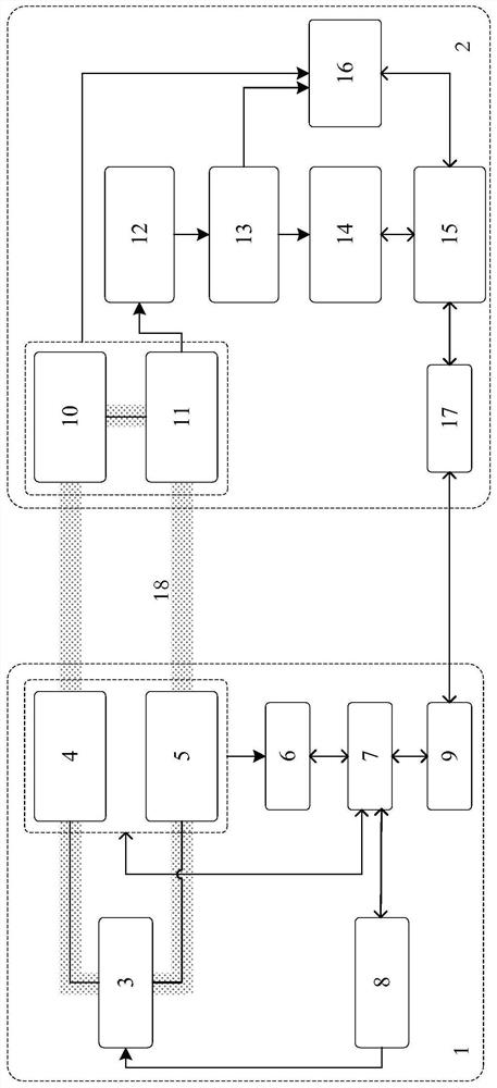
[0066] Zoom in: as Image 6As shown, an electromagnetic echo wireless energy transmission system using a microwave stimulated radiation amplifying device, the power amplifier 3 of the transmitting end 1 can be realized by a microwave stimulated radiation amplifying device, including a pumping module 20 and a microwave stimulated radiation amplifying module 21 Four components, coupling circuit 22 and microwave resonant cavity 23, realize excitation and amplification of electromagnetic echo 18 through the principle of stimulated radiation. The microwave stimulated radiation amplification module 21 is Cu 2 O crystal, the microwave resonator 23 is the quality factor Q≈10 5 metal cavity, the pump module 20 is an optical pump module, and the coupling circuit 22 ensures the coupling input / output of elec...

Embodiment 2

[0075] This embodiment provides an electromagnetic echo wireless energy transmission system based on a power amplifier circuit, the specific content of which is as follows:

[0076] Zoom in: as Figure 11 As shown, an electromagnetic echo wireless energy transmission system using a power amplifying circuit, the power amplifier 3 of the transmitting end 1 is implemented by a power amplifying circuit 24 . The excitation source 8 and the power amplifier circuit 24 ensure that the amplification factor of the signal is controllable. The amplification factor of the power amplifier circuit 24 is generally determined by its circuit parameters, and the excitation source 8 determines the upper limit of the output power.

[0077] Alignment: the same as in Embodiment 1, the first direction tracer 5 and the second direction tracer 10 are direction traceback array antennas, and the first echo receiver 4 and the second echo receiver 11 are the direction traceback array antennas for sending ...

Embodiment 3

[0080] This embodiment provides an electromagnetic echo wireless energy transmission system based on stimulated radiation optical amplification, the specific content of which is as follows:

[0081] Zoom in: as Figure 13 As shown, an electromagnetic echo wireless energy transmission system using a stimulated radiation optical amplifier device, the power amplifier 3 of the transmitting end 1 can be realized by a stimulated radiation optical amplifier device, including a pump module 25 and a stimulated radiation optical amplifier module 26 The two components are used to stimulate and amplify the electromagnetic echo 18 through the principle of stimulated radiation. The pump module 25 can be electrically pumped or optically pumped; the stimulated radiation optical amplification module 26 is a gain medium, including but not limited to Yb:YAG flaky crystals, VECSEL semiconductor gain materials, THz QC-VECSEL crystals, etc.

[0082] Alignment: the first echo receiver 4 and the sec...


PUM


Abstract

The invention relates to a wireless energy transmission system and method for electromagnetic echo excitation amplification. The system comprises a transmitting end and a receiving end, which are usedfor forming an adaptive wireless energy transmission channel. The wireless energy transmission channel constrains the energy of electromagnetic echoes transmitted back and forth within a set lateralrange. Compared with the prior art, the system and method, which are provided by the invention, have the advantages of long-distance movement, human safety, high power transmission and the like.

Description

technical field [0001] The invention relates to the field of energy wireless transmission, in particular to a wireless energy transmission system for electromagnetic echo excitation amplification. Background technique [0002] With the rapid development of mobile communication and computing technology, traditional energy supply solutions such as wired fast charging and energy harvesting can no longer fully meet the new needs of battery life for mobile devices in the Internet of Everything era; therefore, long-distance wireless energy transmission technology has become an urgent need for development. important energy solutions. [0003] Traditional long-distance wireless energy transmission technology has the problem that "high-power electromagnetic waves cannot guarantee human safety during long-distance transmission", and cannot simultaneously meet the three major indicators of "long-distance, high power, and human safety". At present, the widely used magnetic induction wi...

Claims


Application Information

Patent Timeline
Patent Type & Authority Patents(China)
IPC IPC(8): H02J50/27H02J50/23H02J50/60H02J50/90H02J50/80H02J7/00
CPCH02J50/23H02J50/27H02J50/60H02J50/80H02J50/90
Inventor 邓浩刘明清熊明亮刘庆文徐梦圆方稳白云峰
Owner TONGJI UNIV
Why Eureka
Try Eureka