

Laser welding method for realizing rapid splicing of high-strength steel
A technology of laser welding and rapid splicing, applied in laser welding equipment, welding equipment, metal processing equipment, etc., can solve problems such as prolonging production time, reducing production efficiency, and decreasing toughness, so as to reduce the rate of weld fracture and improve production Efficiency and the effect of improving rollability
- Summary
- Abstract
- Description
- Claims
- Application Information
AI Technical Summary
Problems solved by technology
Method used
Image

Examples
Embodiment Construction
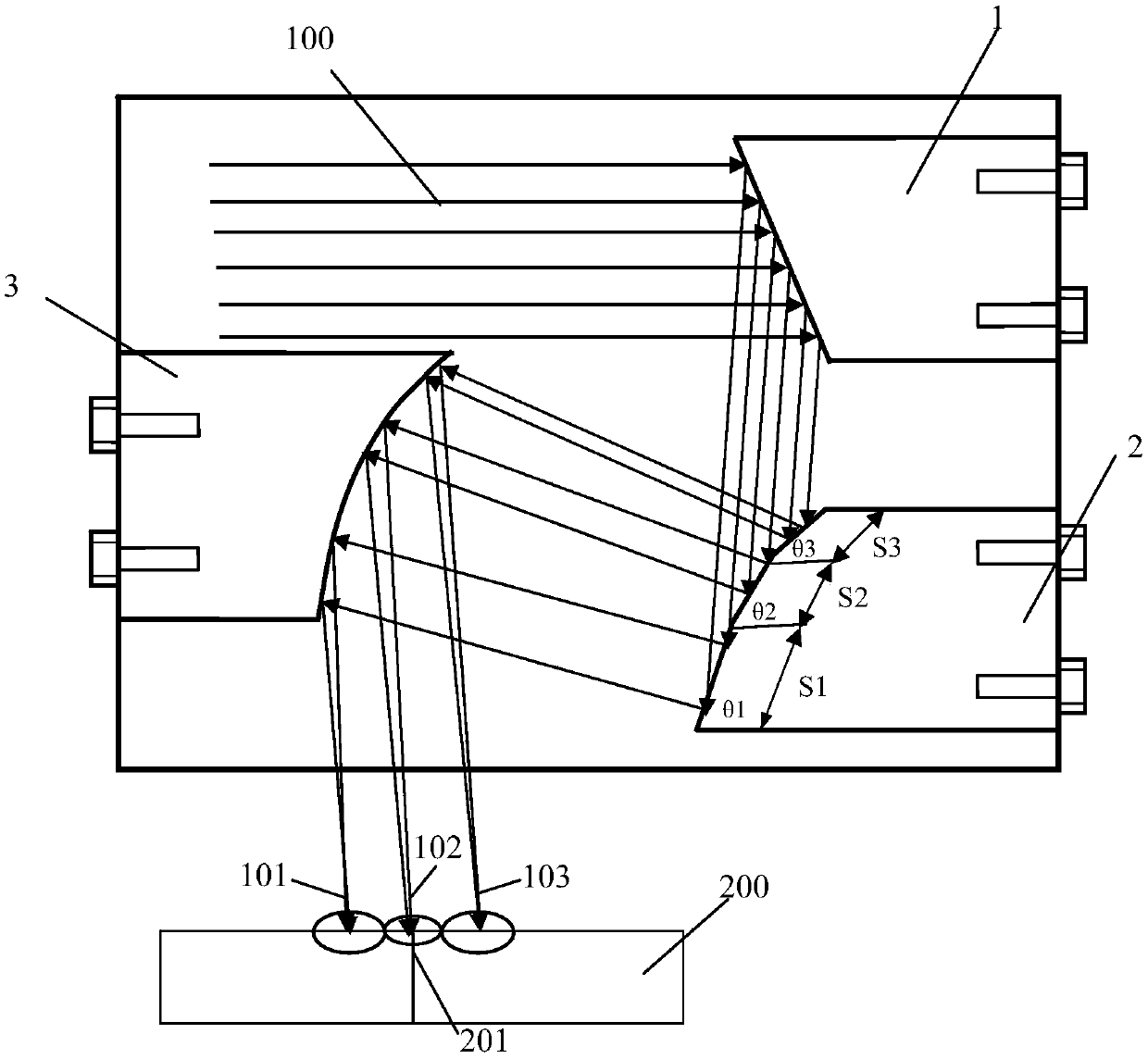
[0033] see figure 1 , figure 2, the present invention realizes the laser welding method of fast splicing of high-strength steel, and it comprises the following steps:
[0034] 1) The two hot coils of high-strength steel are used as the forward coil and the rear coil respectively; the tail of the forward coil and the head of the rear coil are cut by double shears and spliced in the center; the splicing gap is the front coil. The butt gap between the strip tail of the row coil and the strip head of the rear coil after double shearing is 0.05mm-0.30mm;
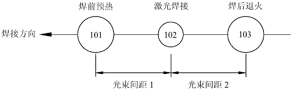
[0035] 2) Using CO 2 laser as a welding laser source, the CO 2 The laser beam 100 of the laser directly enters the spectroscopic device after coming out of the optical path outside the laser source, and the spectroscopic device includes reflector 1-beam splitting mirror 2-focusing mirror 3 in turn; the laser beam forms three laser beams after coming out of the spectroscopic device, wherein the first The laser beam 101 fall...
PUM
 Abstract
Description
Claims
Application Information