Metal ornament surface electroplating treatment device

A technology of electroplating treatment and jewelry, applied in the direction of electrolysis process, electrolysis components, cells, etc., can solve the problems affecting the quality of the plating layer and the surface quality of the electroplating parts, and achieve continuous and effective electroplating treatment, improve the efficiency of electroplating, and reduce the impact Effect

Inactive Publication Date: 2020-01-03
义乌市傅宝仙饰品有限公司
View PDF0 Cites 4 Cited by
  • Summary
  • Abstract
  • Description
  • Claims
  • Application Information

AI Technical Summary

Problems solved by technology

[0003] In the traditional metal jewelry electroplating process, in order to improve the electroplating efficiency, the electrolyte in the electrolytic cell is usually stirred, but this traditional stirring method can easily affect the surface quality of the electroplated parts. At the same time, during the electroplating process, along with the anode Dissolution will also produce mud or slag, which can easily deposit mud and slag on the plated parts by stirring the electrolyte, which will affect the coating quality of the plated parts

Method used


Image

  • Metal ornament surface electroplating treatment device
  • Metal ornament surface electroplating treatment device
  • Metal ornament surface electroplating treatment device

Examples


Embodiment 1

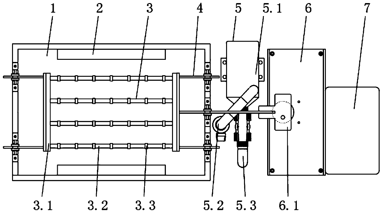
[0030] Embodiment one, with reference to Figure 1-2 , a metal jewelry surface electroplating treatment device, comprising an electroplating pool 1, an anode 2, a cathode 3, a rectifier 7 and a base 8, the electroplating pool 1 is respectively provided with an anode 2, a cathode 3, and the cathode 3 is erected on the electroplating plate through a guide mechanism 4 At the middle position of the pool 1, a base 8 is provided under the bottom of the electroplating pool 1, and a filter unit 5 and a swing mechanism 6 are arranged on one side of the electroplating pool 1 on the base 8 in turn, and a rectifier 7 is provided on one side of the base 8, and a cathode 3 is provided The guiding mechanism 4 is erected in the electroplating pool 1, and used in conjunction with the swing mechanism 6, so that the cathode 3 and the hanging ornaments swing regularly in the electroplating pool 1 at low frequency, thereby accelerating the convection of the solution and consuming near the cathode 3...

Embodiment 2

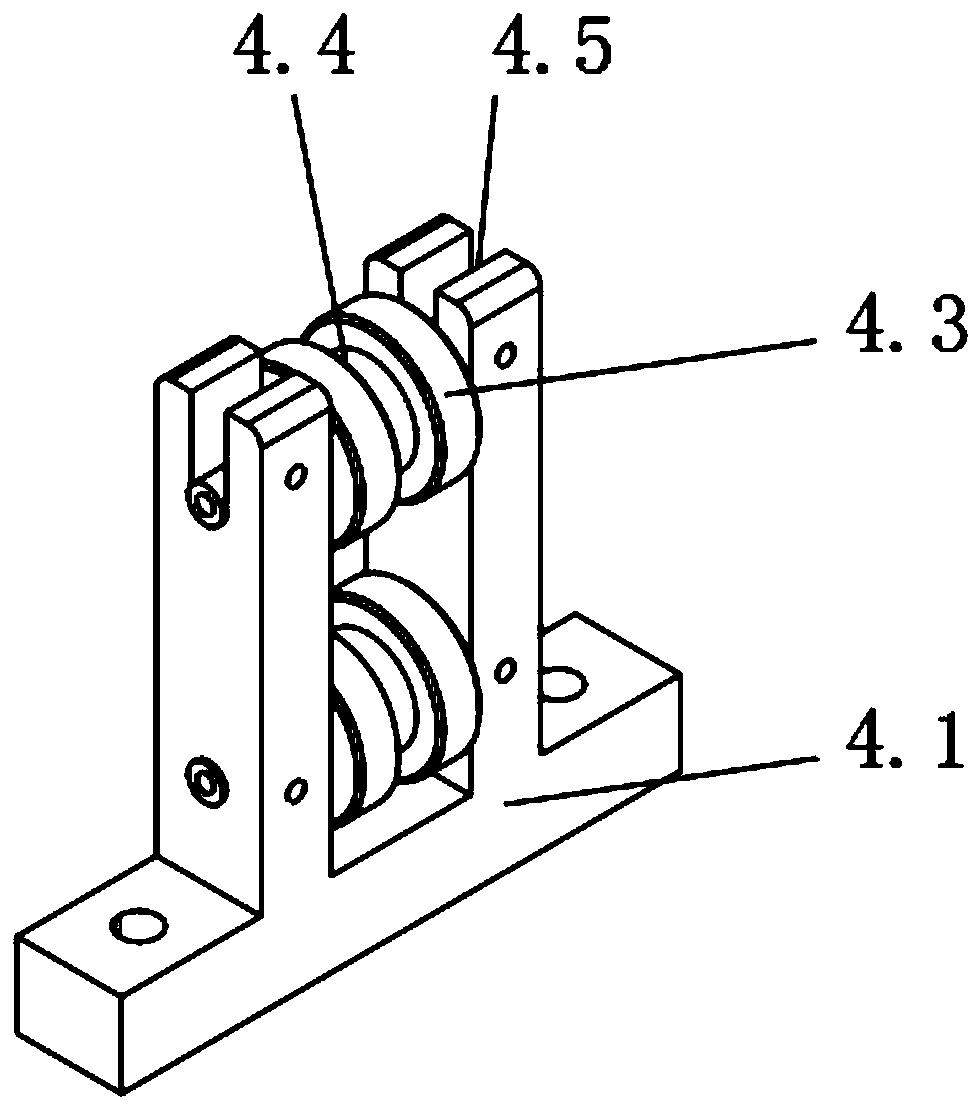
[0031] Embodiment two, refer to Figure 1-3 and Figure 4 , the guide mechanism 4 includes a support seat 4.1, a guide rod 4.2, and a guide wheel 4.3, and the support seat 4.1 is provided with two guide wheels 4.3 from bottom to top, the lower guide wheel 4.3 is fixedly connected with the support seat 4.1 through a pin shaft, and the upper part is fixed through a pin The shaft and the limit groove 4.5 on the top of the support seat 4.1 are clamped, and the middle position of the surface of the guide wheel 4.3 is provided with a groove 4.4 for use with the guide rod 4.2 to ensure the reciprocating movement of the cathode 3 in the electroplating tank 1 and better cooperate with the swing Normal use of mechanism 6.

Embodiment 3

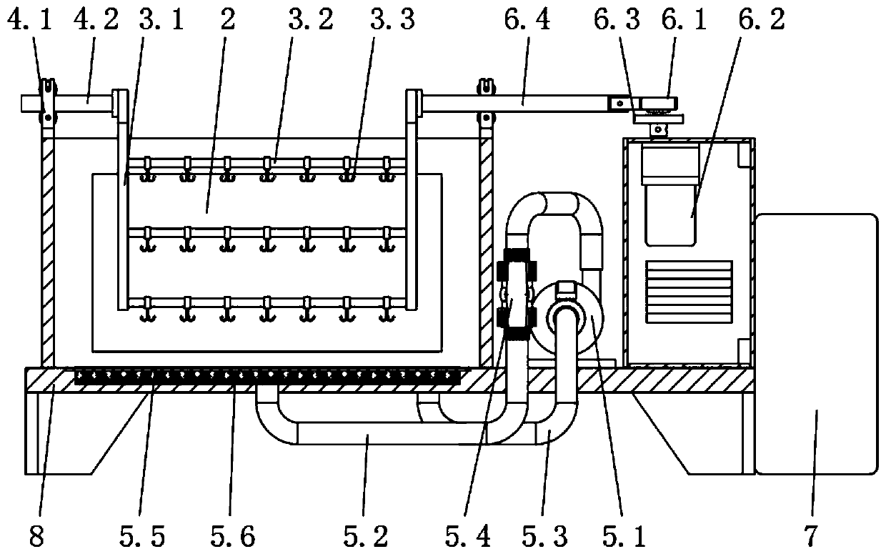
[0032] Embodiment three, refer to Figure 1-2 and Figure 5-6 , the swing mechanism 6 includes a swing member 6.1, a drive motor 6.2, a driving wheel 6.3, a swing rod 6.4, and a driven wheel 6.5, and a guide groove 6.6 is provided on the surface of the swing member 6.1, and the drive motor 6.2 is installed above the inside of the control box, and the drive motor The driving wheel 6.3 is installed above the driving wheel 6.3, and the driven wheel 6.5 is installed eccentrically on the upper surface of the driving wheel 6.3, and the upper part of the driven wheel 6.5 is connected to the swing member 6.1 through the guide groove 6.6, and the side of the swing member 6.1 is connected to the guide mechanism 4 through the swing rod 6.4 The driving motor 6.2 drives the driven wheel 6.5 eccentrically connected to the driving wheel 6.3 to rotate, and the driven wheel 6.5 interacts with the guide groove 6.6 in the swinging member 6.1, so that the swinging member 6.1 and the cathode 3 con...


PUM


Abstract

The invention discloses a metal ornament surface electroplating treatment device. The device comprises an electroplating tank, an anode, a cathode, a rectifier and a base, wherein the anode and the cathode are arranged in the electroplating tank, the cathode is erected at the middle position in the electroplating tank through a guiding mechanism, the base is arranged below the electroplating tank,one side, located on the base, of the electroplating tank is sequentially provided with a filtering unit and a swinging mechanism, and the rectifier is arranged on one side of the base. According tothe device, the arranged cathode is erected in the electroplating tank through the guiding mechanism to cooperate with the swinging mechanism, and the cathode and an ornament hung on the cathode swingin a regular low-frequency manner in the electroplating tank, so that convection of solution is accelerated, metal ions consumed in the vicinity of the cathode are timely supplemented, concentrationpolarization effect of the cathode is reduced, the electroplating efficiency of the metal ornament is improved, through the low-frequency cathode movement mode, the defect that mud and slag are proneto deposit on a plated piece is overcome, and the electrode reaction speed is improved while the electroplating quality is ensured.

Description

technical field [0001] The invention relates to the technical field of metal electroplating, in particular to a surface electroplating treatment device for metal ornaments. Background technique [0002] Jewelry refers to ornaments worn on the head. Jewelry now widely refers to bird hairpins, earrings, necklaces, rings, bracelets, etc. processed from precious metals and gemstones. Jewelry is generally used to decorate the human body, and also has the meaning of expressing social status, wealth and identity. The electroplating process is a method of covering a conductor with a layer of metal using the principle of electrolysis. Electroplating refers to a surface processing method in which the cations of the pre-plated metal in the plating solution are deposited on the surface of the base metal by electrolysis with the base metal to be plated as the cathode in a salt solution containing pre-plated metal to form a coating. . [0003] In the traditional metal jewelry electrop...

Claims


Application Information

Patent Timeline
Patent Type & Authority Applications(China)
IPC IPC(8): C25D21/10C25D21/06C25D21/18C25D17/00
CPCC25D17/00C25D21/06C25D21/10C25D21/18
Inventor 朱永红王起任大龙
Owner 义乌市傅宝仙饰品有限公司
Why Eureka
Try Eureka