Current collector and manufacturing method thereof
A current collector and three-dimensional technology, which is applied in the direction of electrode carriers/collectors, electrical components, battery electrodes, etc., can solve the problem of weak connection between electrode materials and current collectors, affecting the performance of the electrochemical system, and the electronic conduction ability of electrode pole pieces Poor problems, to achieve the effect of ensuring electrochemical performance, improving electronic conduction ability, and increasing bonding strength
- Summary
- Abstract
- Description
- Claims
- Application Information
AI Technical Summary
Problems solved by technology
Method used
Image
Examples
preparation example Construction
[0036] Another object of the present invention is to provide a method for preparing a current collector, the method comprising the steps of:
[0037] S1: Mix conductive material, polymer binder, conductive polymer and solvent, emulsify and grind to obtain conductive coating slurry;
[0038] S2: Perform surface roughening pretreatment on the base layer to obtain a pretreated base layer;
[0039]S3: Using a positive-phase printing coater with a regular three-dimensional grid structure plate roller, the conductive coating slurry is coated on the surface of the pretreated base layer, and baked and dried at 50°C to 200°C to obtain current collector.
[0040] Among them, the material selection of conductive material, polymer binder, conductive polymer and base layer is the same as above, and will not be repeated in this paper; the mass percentage range of conductive material is 20% to 80%; the quality of polymer binder The percentage range is 1% to 40%; the mass percentage range o...
Embodiment 1
[0048] S1: Mix 9g of carbon black, 3.5g of modified polyurethane, 2.5g of polythiophene and 85g of N-methylpyrrolidone, emulsify and grind to obtain a conductive coating slurry;
[0049] S2: Perform solution cleaning, corona, and high-temperature annealing on the aluminum foil of the base layer in sequence to obtain a pretreated aluminum foil;
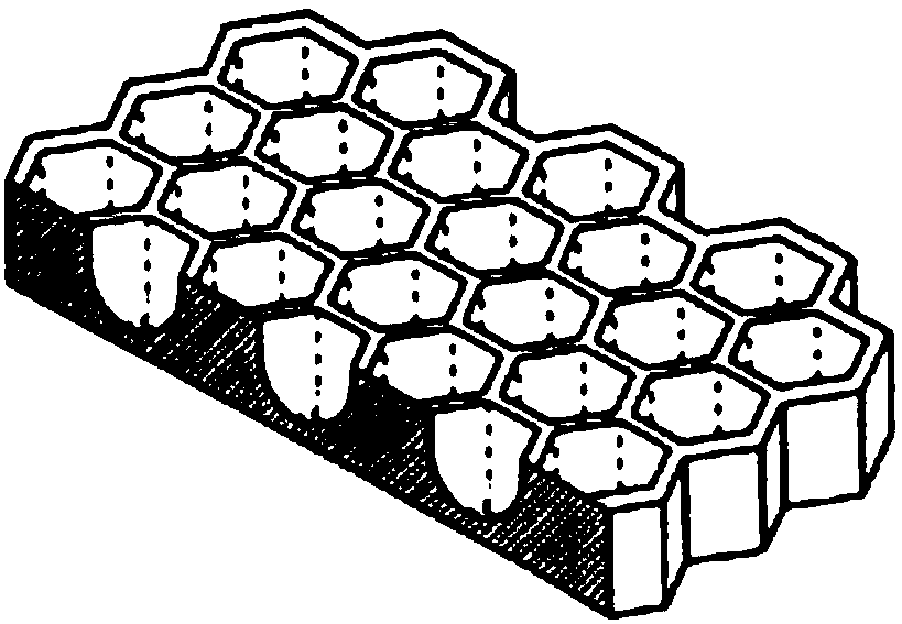
[0050] S3: Add the conductive coating slurry into the feed tank of the coating machine, and use a positive phase printing coating machine with a regular three-dimensional hexagonal grid structure plate (the grid structure on the plate roll is 250 mesh, engraved The depth is 15 μm), the conductive coating slurry is coated on the surface of the pretreated aluminum foil, and baked and dried at 120 ° C, the coating speed is 120 m / min, and the finished product is wound up to obtain a conductive coating thickness of 0.7 μm, a current collector with a hexagonal lattice structure on the surface.
[0051] see figure 2 As shown, the conductiv...
Embodiment 2
[0059] S1: Mix 3g carbon black, 6g polyacrylic acid, 6g polythiophene and 85g N-methylpyrrolidone, emulsify and grind to obtain a conductive coating slurry;
[0060] S2: Perform solution cleaning, corona, and high-temperature annealing on the aluminum foil of the base layer in sequence to obtain a pretreated aluminum foil;
[0061] S3: Add the conductive coating slurry into the feed tank of the coating machine, and use a positive-phase printing coating machine with a regular three-dimensional diamond-shaped grid structure plate roll (the grid structure on the plate roll is 200 mesh, and the engraving depth is 20 μm), the conductive coating slurry is coated on the surface of the pretreated aluminum foil, and baked and dried at 120 ° C, the coating speed is 150 m / min, and the finished product is wound to obtain a conductive coating with a thickness of 0.5 μm. A current collector with a diamond lattice structure on the surface.
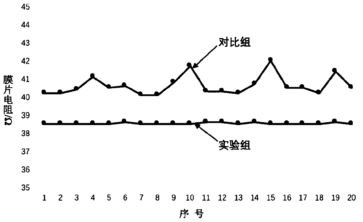
[0062] The process of testing the current collect...
PUM
| Property | Measurement | Unit |
|---|---|---|
| width | aaaaa | aaaaa |
| viscosity | aaaaa | aaaaa |
| peel strength | aaaaa | aaaaa |
Abstract
Description
Claims
Application Information
 - R&D
- Intellectual Property
- Life Sciences
- Materials
- Tech Scout
- Unparalleled Data Quality
- Higher Quality Content
- 60% Fewer Hallucinations
Browse by: Latest US Patents, China's latest patents, Technical Efficacy Thesaurus, Application Domain, Technology Topic, Popular Technical Reports.
© 2025 PatSnap. All rights reserved.Legal|Privacy policy|Modern Slavery Act Transparency Statement|Sitemap|About US| Contact US: help@patsnap.com


