Eureka AIR delivers breakthrough ideas for toughest innovation challenges, trusted by R&D personnel around the world.

Precise ammonia spraying device and method for thermal power plant denitration SCR reactors

A technology for SCR reactors and thermal power plants, applied in chemical instruments and methods, separation methods, gas treatment, etc., can solve problems such as lag, long pipelines, and large ammonia escape, and achieve the effect of large sampling range and simple structure

Pending Publication Date: 2020-01-17
CHINA HUADIAN ENG +1
View PDF6 Cites 3 Cited by
  • Summary
  • Abstract
  • Description
  • Claims
  • Application Information

AI Technical Summary

Problems solved by technology

The above factors will lead to the overall NH in the SCR reactor 3 / NO X mismatch, leading to large differences in local denitrification efficiency, which affects the overall ammonia escape and makes the ammonia escape larger
[0003] Traditional SCR export NO X Single-point sampling, 2-4 monitoring points or multi-point sampling measurement, such as the plan announced by the application number 201520975504.5, the sampling port is set on the side wall of the denitrification SCR reaction zone channel, and the measurement is the flue gas group near the side wall of the SCR reaction zone The measured value cannot represent the average concentration and concentration distribution of the entire cross-section. CEMS (Continuous Emission Monitoring System) has a long sampling pipeline, especially during the load-up and down-load stages of the unit. The amount of ammonia injected automatically tracked by the SCR system will Lag the amount of ammonia injection actually required on site, and the measurement lag time generally reaches 2-3min

Method used


Image

  • Precise ammonia spraying device and method for thermal power plant denitration SCR reactors
  • Precise ammonia spraying device and method for thermal power plant denitration SCR reactors
  • Precise ammonia spraying device and method for thermal power plant denitration SCR reactors

Examples


Embodiment 1

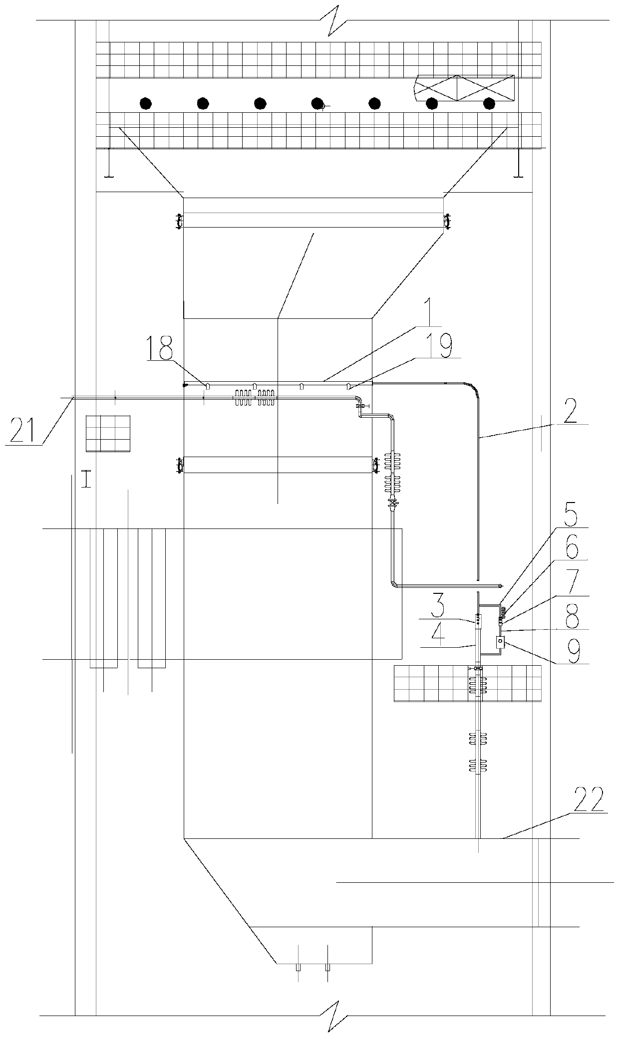
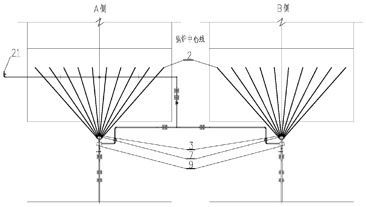
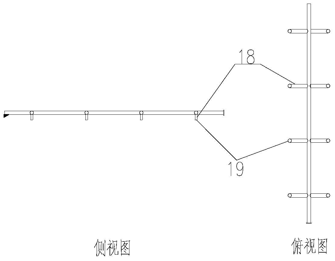
[0037] Embodiment 1 of the present invention: as Figure 1-5 As shown, a precision ammonia injection device for denitrification SCR reactor in a thermal power plant includes an SCR reactor, a flue gas extraction analysis system and an ammonia injection grid partition system. The flue gas extraction analysis system is arranged at the outlet of the SCR reactor. Including the flue internal sampling pipe system and the flue external analysis system; the flue internal sampling pipe system includes 10 samplers 1, 10 sampling branch pipes 2 connected to the sampler 1, and the sampling branch pipes 2 are converged and connected to the sampling mixer 3 , the other end of the sampling mixer 3 is connected to the sampling mixing pipe 4, and the flue gas is connected to the inlet flue 22 of the air preheater through the sampling mixing pipe 4; Mixer 7, the other end of the analysis mixer 7 is sequentially connected to the analysis mixing pipe 8 and the analyzer 9; the inlet of the analysi...

Embodiment 2

[0043] Embodiment 2: as figure 1 , 2 As shown in and 4, a precision ammonia injection device for denitrification SCR reactor in a thermal power plant includes an SCR reactor, a flue gas extraction analysis system and an ammonia injection grid partition system, and the flue gas extraction analysis system is arranged at the outlet of the SCR reactor place, including the internal sampling pipe system of the flue and the analysis system outside the flue; the internal sampling pipe system of the flue includes 12 samplers 1, and 12 sampling branch pipes 2 connected to the sampler 1, and the sampling branch pipes 2 are converging and connected to the sampling mixing 3, the other end of the sampling mixer 3 is connected to the inlet flue 22 of the air preheater; the analysis system outside the flue includes 12 analysis branch pipes 5, the analysis branch pipes 5 are converged and connected to the analysis mixer 7, and the other end of the analysis mixer 7 is connected to Analyzer 9; ...

Embodiment 3

[0044] Embodiment 3: as Figure 1-4 As shown, a precision ammonia injection device for denitrification SCR reactor in a thermal power plant includes an SCR reactor, a flue gas extraction analysis system and an ammonia injection grid partition system. The flue gas extraction analysis system is arranged at the outlet of the SCR reactor. Including flue internal sampling pipe system and flue external analysis system; said flue internal sampling pipe system includes 8 samplers 1, 8 sampling branch pipes 2 connected with sampler 1, sampling branch pipes 2 converged and connected to sampling mixer 3 , the other end of the sampling mixer 3 is connected to the inlet flue 22 of the air preheater; the analysis system outside the flue includes 8 analysis branch pipes 5, the analysis branch pipes 5 are converged and connected to the analysis mixer 7, and the other end of the analysis mixer 7 is connected to the analyzer 9; the inlet of the analysis branch pipe 5 is arranged on the pipeline...


PUM

PropertyMeasurementUnit
Lengthaaaaaaaaaa

Abstract

The invention relates to a precise ammonia spraying device and a method for thermal power plant denitration SCR reactors. The precise ammonia spraying device comprises a flue gas extraction and analysis system and an ammonia spraying grid partitioning system; the flue gas extraction and analysis system comprises a sampler; the sampler is connected with a sampling branch pipe; an analysis branch pipe is derived from the sampling branch pipe and is designed to stretch into an analyzer; an ammonia spraying grid subarea comprises an ammonia spraying main pipe, the ammonia spraying main pipe is divided into ammonia spraying subarea branch pipes, ammonia flowmeters and subarea leveling valves are arranged on the ammonia spraying subarea branch pipes, and the subarea leveling valves are connectedwith bypass subarea leveling valves in parallel; measurement data obtained by the flue gas extraction and analysis system is used for adjusting ammonia spraying grid ammonia spraying amount. According to the precise ammonia spraying device and the method for denitration SCR reactors, the sampling measurement value can represent the average NOX concentration and NOX concentration distribution of the whole section, and the ammonia spraying amount automatically tracked by an SCR system is coincide with the ammonia spraying amount actually needed on site.

Description

technical field [0001] The invention relates to the technical field of environmental protection, in particular to a precise ammonia injection device and method for a denitrification SCR reactor in a thermal power plant. Background technique [0002] In the flue gas SCR (Selective Catalytic Reduction) system, the flue comes out of the boiler economizer into two channels, and there are continuous 90° bends and lateral oblique expansions, the flue gas flow field is uneven, and it is easy to Make regional ammonia injection rate and NO X The amount does not match, resulting in NO in some areas in the outlet flue X The concentration exceeds the standard, and in some areas NH 3 High escape rate. The measurement technology of ammonia slip rate is very difficult. The ammonia slip is not only related to the design characteristics of the SCR itself, but also closely related to the operating conditions of the SCR. The flue gas velocity field in the SCR reactor, the NO X Concentratio...

Claims


Application Information

Patent Timeline
IPC IPC(8): B01D53/90B01D53/86B01D53/56
CPCB01D53/90B01D53/8631B01D2258/0283Y02E20/34
Inventor 王争荣汪洋李伟王桦
Owner CHINA HUADIAN ENG
Why Eureka
Eureka Blog
Learn More