A self-calibration method of two-dimensional table error based on machine vision

A machine vision and workbench technology, applied in instruments, computer parts, image analysis, etc., can solve the problems of measurement accuracy, such as large influence, large influence, and high price of alignment error of line ruler, so as to improve the measurement accuracy. Efficiency, continuous dynamic measurement, the effect of reducing the amount of calculation

Active Publication Date: 2022-07-12
HUAZHONG UNIV OF SCI & TECH
View PDF4 Cites 0 Cited by
  • Summary
  • Abstract
  • Description
  • Claims
  • Application Information

AI Technical Summary

Problems solved by technology

Optical measurement methods often require high-precision measurement equipment and optical components such as laser interferometers, laser trackers, mirrors, prisms, etc., but the above-mentioned detection instruments are expensive, and the measurement process is complicated and greatly affected by the environment.
[0005] The second is to use standard parts for error detection, such as the literature "Luo P F, Pan S P, Chu TC. Application of computer vision and laser interferometer to the inspection of line scale [J]. Optics and Lasers in Engineering, 2004, 42(5) :563-584” puts forward the method of applying machine vision to detect the axial positioning error with the linear ruler as the standard part, which takes the center line of the stripe width of the linear ruler as the standard, and takes the pixel deviation of the center line as the axial positioning error, and at the same time The laser interferometer is used to detect the axial positioning error to verify the accuracy of the method, but the measurement accuracy is greatly affected by the square error of the linear scale; the literature "Zou D H, Jia R Q, Zhang C. Precision Compensation Method for Positioning Error of WorkbenchBased on Machine Vision[J].Laser&Optoelectronics Progress, 2018.5" proposed a compensation method for the positioning error of the working platform of the image measuring instrument by using a standard array of solid circular plates. Overlap, and record the current position, obtain the fitting coefficient through polynomial fitting, and use it to compensate for the positioning error of the workbench. After compensation, the positioning accuracy of the workbench is 2 μm, but there are also alignment errors and manufacturing errors of the ball plate; the literature "Ye J, Takac M, Berglund CN, et al.Exact algorithm self-calibration of two-dimensional precision metrology stages[J].Precision Engineering,1997,20(1):16-32"proposed a two-dimensional workbench based on Fourier transform The error self-calibration algorithm, which needs to measure three different position views of the standard grid plate, but the algorithm is greatly affected by noise, and the robustness is poor; domestic and foreign scholars have compared the self-calibration algorithm proposed by J.Ye and M.Takac Improvements were made to propose a self-calibration method for two-dimensional workbench system errors using least squares and iterative methods, but it needs to measure the grid plate at several different positions, and there are position errors and rotation deviations in each position that cannot be eliminated
In the process of using standard parts to calibrate and compensate the working error of the image measuring instrument, there are problems that the manufacturing deviation and position deviation of the standard parts cannot be eliminated.

Method used


Image

  • A self-calibration method of two-dimensional table error based on machine vision
  • A self-calibration method of two-dimensional table error based on machine vision
  • A self-calibration method of two-dimensional table error based on machine vision

Examples


Embodiment 1

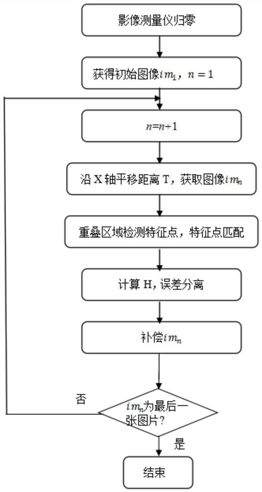
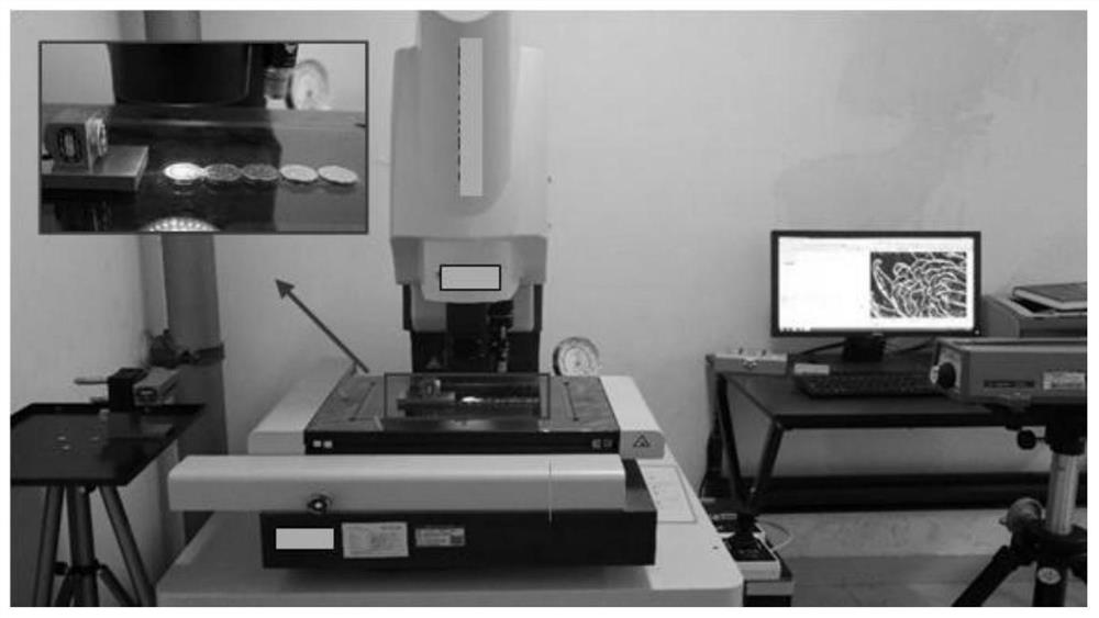
[0054] S1 image acquisition steps: reset the image measuring instrument to zero, take the coins in a column along the X axis of the worktable and then focus, take the first picture im at the CCD camera coordinates (0,0,Z) 1 , the resolution of the picture is 1024 × 1280; then the CCD camera moves along the X axis for a distance of 5mm, and the CCD camera coordinates Y and Z values ​​remain unchanged when moving along the X axis, the measurement range is 0-100mm, and a total of 21 pictures are obtained ; During the movement, the CCD camera does not focus repeatedly, and makes the picture taken at the current position overlap with the picture taken at the previous position by about 40%;

[0055] S2 image processing step: perform error compensation on the acquired image according to the aforementioned method, and complete the error self-calibration of the two-dimensional workbench;

[0056] S3 accuracy verification: to verify the accuracy of the two-dimensional workbench error de...


PUM


Abstract

The invention belongs to the field of machine tool error detection, and specifically discloses a two-dimensional workbench error self-calibration method based on machine vision. Picture; S2 obtains the corresponding feature point sets of the nth and n+1th pictures, obtains the homography transformation matrix according to the corresponding feature point set, and separates them from the pre-built error separation model according to the homography transformation matrix Obtain the error value, and perform error compensation on the n+1th picture with this error value, n=1; S3 performs the error compensation on the n+1th picture and the n+2th picture according to the method in S2. Error compensation is performed on 2 pictures; S4 n=n+1, and S3 is repeated until the error compensation for the last picture is completed, thereby realizing error self-calibration. The invention realizes continuous dynamic error measurement, and simultaneously measures multiple geometric errors, with high measurement accuracy and high speed.

Description

technical field [0001] The invention belongs to the field of machine tool error detection, and more particularly relates to a two-dimensional workbench error self-calibration method based on machine vision. Background technique [0002] With the rapid development of modern manufacturing technology, product size is also developing in the direction of small and ultra-precision, and at the same time, higher requirements are placed on measurement accuracy and detection speed. As an advanced and efficient non-contact measurement method, image measurement technology based on machine vision is widely used in different fields such as electronics, machinery, medical treatment, aviation, etc. Pick and so on. [0003] When the image measuring instrument detects the workpiece, the object to be measured is moved through the two-dimensional worktable, and then the optical imaging system performs rapid scanning and detection. However, the return error of the lead screw and the geometric ...

Claims


Application Information

Patent Timeline
Patent Type & Authority Patents(China)
IPC IPC(8): G06T7/80G06T7/00G06T7/33G06V10/75G06K9/62
CPCG06T7/80G06T7/0004G06T7/33G06V10/751
Inventor 王健赵文义卢文龙周莉萍刘晓军
Owner HUAZHONG UNIV OF SCI & TECH
Why Eureka
Try Eureka