Control method of multiphase motor driving topology with suspension capacitor

A suspension capacitor and motor drive technology, which is applied in motor generator control, electronic commutation motor control, motor control, etc., can solve the problems of inapplicability and less control dimensions, and achieve extended life, stable working status, and reliable torque. control effect

Inactive Publication Date: 2020-01-17
HUAZHONG UNIV OF SCI & TECH
View PDF3 Cites 1 Cited by
  • Summary
  • Abstract
  • Description
  • Claims
  • Application Information

AI Technical Summary

Problems solved by technology

[0006] The present invention provides a multi-phase motor drive topology control method with a floating capacitor, which is used to solve the problem that the existing three-phase motor drive topology control method with a floating capacitor has fewer control dimensions and the floating capacitor requires specific constraints for real-time control. Technical issues that cannot be applied in the scene

Method used


Image

  • Control method of multiphase motor driving topology with suspension capacitor
  • Control method of multiphase motor driving topology with suspension capacitor
  • Control method of multiphase motor driving topology with suspension capacitor

Examples


Embodiment 1

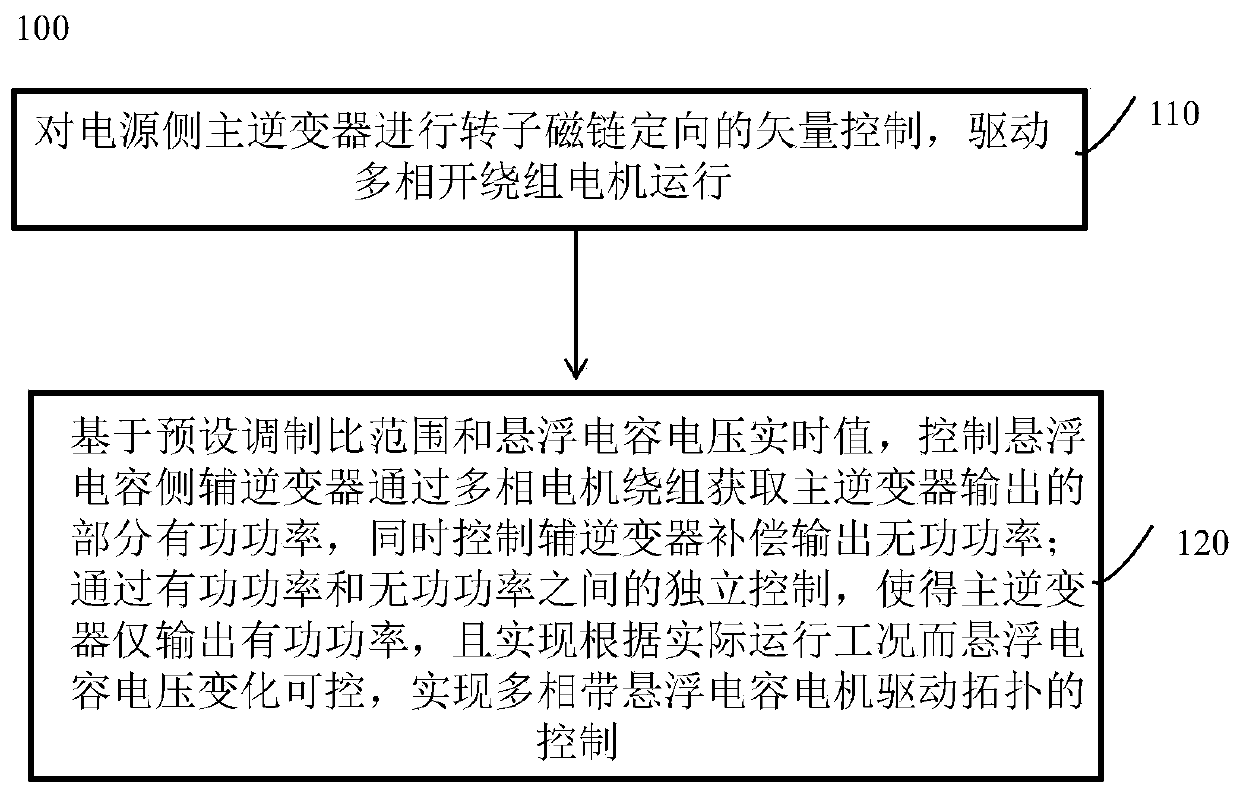
[0042] A control method 100 for a multi-phase motor drive topology with a floating capacitor, such as figure 1 shown, including:

[0043] Step 110, performing vector control of the rotor flux linkage orientation on the main inverter on the power supply side, and driving the multi-phase open-winding motor to run;

[0044] Step 120, based on the preset modulation ratio range and the real-time value of the floating capacitor voltage, control the auxiliary inverter on the floating capacitor side to obtain part of the active power output by the main inverter through the multi-phase motor winding, and at the same time control the auxiliary inverter to compensate the output reactive power power; through the independent control between active power and reactive power, the main inverter only outputs active power, and realizes the controllable change of the floating capacitor voltage according to the actual operating conditions, realizing the multi-phase motor drive topology with floati...

Embodiment 2

[0091] A multi-phase motor drive topology system with floating capacitors, such as Figure 9 As shown, it includes: a controller, and a main inverter on the power supply side respectively connected to the controller (the power supply voltage is V dc ), the floating capacitor side auxiliary inverter (the capacitor voltage is V cap ) and a multi-phase motor (the number of phases is n); wherein, each phase of the main inverter on the power supply side, the auxiliary inverter on the suspension capacitor side and the multi-phase motor is connected in sequence, and the controller is used to perform the above-described first embodiment A control method for any multiphase motor drive topology with a floating capacitor. In the figure, g 1 and g 2 Represents the reference ground potential of the main and auxiliary inverters.

[0092] The relevant technical solutions are the same as those in Embodiment 1, and will not be repeated here.

Embodiment 3

[0094] A storage medium, in which instructions are stored, and when a computer reads the instructions, the computer is made to execute any one of the above-mentioned control methods for multi-phase motor drive topologies with floating capacitors.

[0095] The relevant technical solutions are the same as those in Embodiment 1, and will not be repeated here.


PUM


Abstract

The invention discloses a control method of a multiphase motor driving topology with a suspension capacitor. The method comprises the following steps of performing vector control of rotor flux linkageorientation on a power supply side main inverter to drive a multiphase open winding motor to operate; based on a preset modulation ratio range and a voltage real-time value of the suspension capacitor, independently controlling a suspension capacitor side auxiliary inverter to obtain part of active power outputted by the main inverter through a multi-phase motor winding, and independently controlling the auxiliary inverter to compensate the output reactive power, so that the main inverter only outputs the active power, and the voltage change of the suspension capacitor is controllable according to the actual operation condition. According to the invention, by combining the characteristics of a power supply side and two control cores (capacitor voltage controllability and reactive power compensation) of a capacitor side, and adopting the hybrid mode of main inverter torque flux linkage decoupling and auxiliary inverter active and reactive decoupling, it is guaranteed that the working state of the capacitor side auxiliary inverter is stable, the advantage of reactive compensation of the capacitor side auxiliary inverter is brought into play to the maximum extent, the switching lossof the suspended capacitor side inverter is effectively reduced, and the system efficiency is improved.

Description

technical field [0001] The invention belongs to the field of motor control, and more specifically relates to a control method for driving topology of a multi-phase motor with a floating capacitor. Background technique [0002] Due to the global energy crisis brought about by fossil energy and environmental pollution that cannot be ignored, the development and utilization of clean energy has become a core issue in the energy industry. However, various forms of energy cannot be used directly. Electric energy is the most suitable form of energy for all clean energy such as wind energy and tidal energy. Therefore, the rapid development of the renewable energy power generation industry has promoted the consumption of electricity. Research on electric traction and transmission technology. [0003] However, after many years of development, the traditional motor theory and electric drive control technology can no longer meet the increasing industrial demand. New motors, drive topol...

Claims


Application Information

Patent Timeline
Patent Type & Authority Applications(China)
IPC IPC(8): H02P21/00H02P27/06H02P29/50H02P25/02
CPCH02P21/00H02P25/02H02P27/06H02P29/50
Inventor 刘自程孙翔文李安蒋栋曲荣海
Owner HUAZHONG UNIV OF SCI & TECH
Why Eureka
Try Eureka