
Double-arc auxiliary laser welding device and method

A technology of welding device and laser device, which is applied in the direction of laser welding equipment, welding equipment, metal processing equipment, etc., can solve the problems of fine grain in weld structure, high welding penetration ratio, unfavorable metal spreading, etc., and achieve the reduction of molten pool Effects of cooling rate, increased welding speed, and improved wettability and spreadability

Inactive Publication Date: 2020-01-31
清远市世辰科技有限公司 +1
View PDF0 Cites 4 Cited by
  • Summary
  • Abstract
  • Description
  • Claims
  • Application Information

AI Technical Summary

Problems solved by technology

[0002] Aluminum / steel dissimilar metals are widely used in the automotive industry. Due to the poor weldability of aluminum and steel, it is difficult to achieve high-quality connection of aluminum / steel dissimilar metals by traditional welding methods. Appropriate welding methods must be used. Compared with the traditional welding process, laser welding has the characteristics of energy concentration, high welding penetration ratio, small welding deformation, fine grain grains of the weld seam formed, and high welding efficiency. It has been widely used, but the conventional single heat source laser welding technology Due to the narrow heating width, it is not conducive to the spreading of the metal, which can no longer meet the requirements of actual production.

Method used


Image

  • Double-arc auxiliary laser welding device and method
  • Double-arc auxiliary laser welding device and method
  • Double-arc auxiliary laser welding device and method

Examples


Embodiment

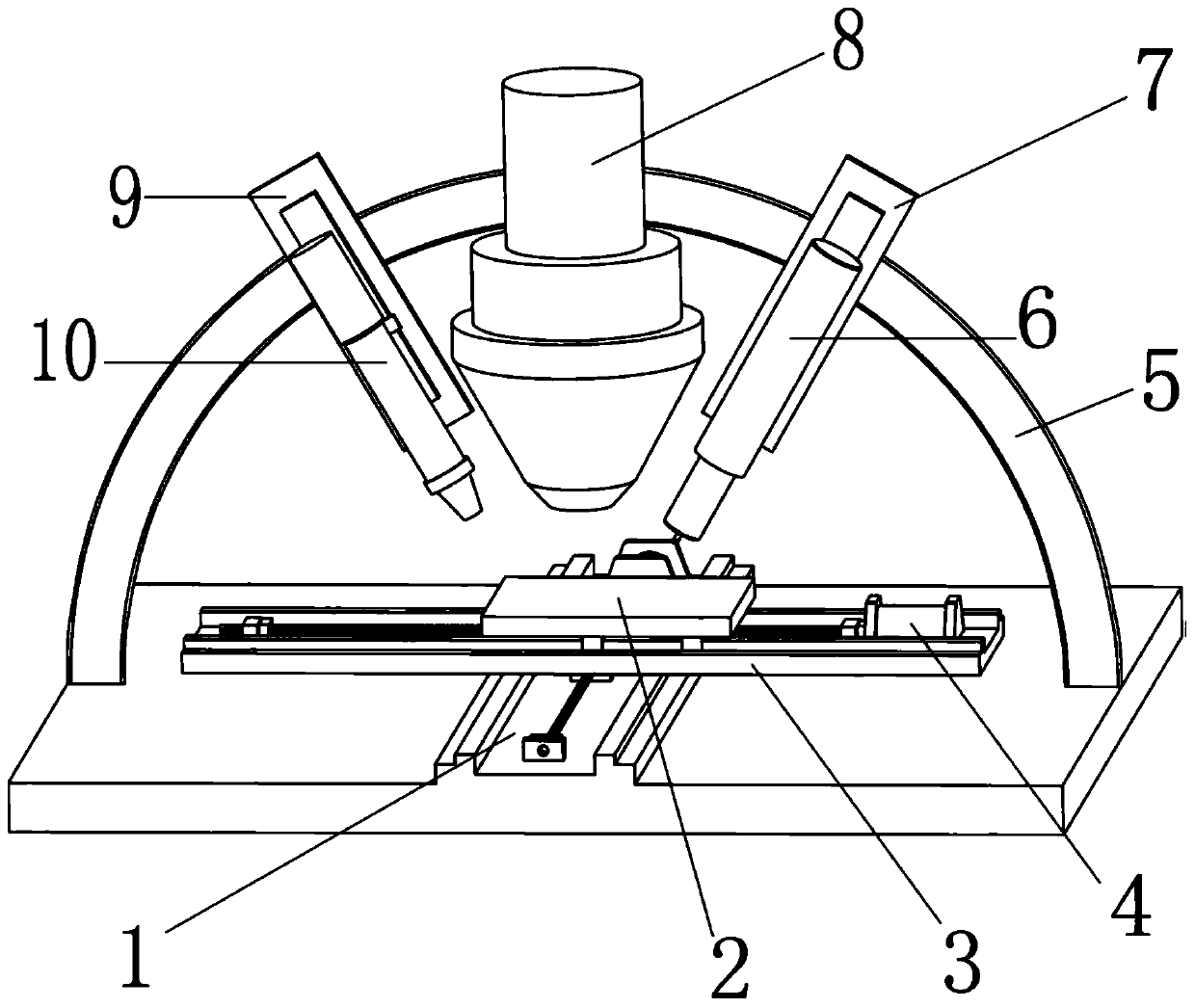
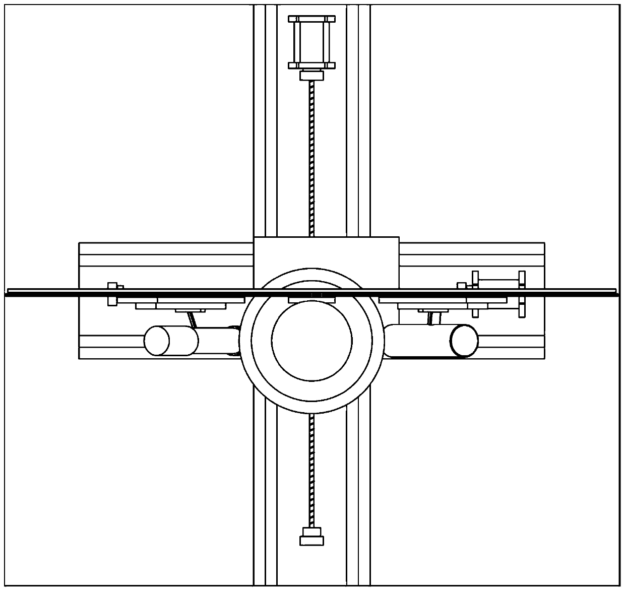
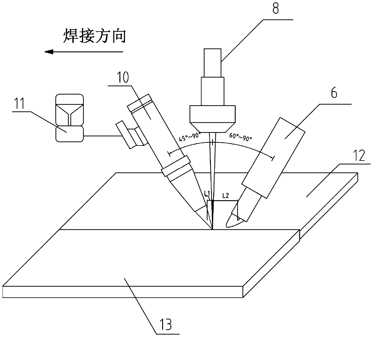
[0035] Such as figure 1 , figure 2 shown, combined with image 3 As shown, this embodiment provides a dual-arc assisted laser welding device, including: Y-axis sliding guide rail 1, welding table 2, X-axis sliding guide rail 3, stepping motor 4, annular sliding guide rail 5, TIG welding device 6, TIG welding sliding guide rail 7, laser device 8, plasma arc welding torch guide rail 9, plasma arc welding device 10 and coaxial powder feeding device 11;

[0036] In this embodiment, the laser device 8, the plasma arc welding device 10 and the TIG welding device 6 are fixedly arranged on the corresponding preset positions of the circular guide rail, and the microcomputer system controls the stepper motor to drive the two-way screw to move through the pre-designed path , the two-way screw adjusts the movement of the Y-axis sliding guide rail 1 and the X-axis sliding guide rail 3, and then controls the movement of the welding table 2, and the double-arc assisted laser welding devic...


PUM


Abstract

The invention discloses a double-arc auxiliary laser welding device and method. The device comprises a welding worktable, a horizontal plane moving device, a base, a ring-shaped sliding rail, a TIG welding sliding guide rail, a laser guide rail, a plasma arc welding gun guide rail, a coaxial powder sending device, a TIG welding device, a laser device and a plasma arc welding device, wherein the TIG welding device, the laser device and the plasma arc welding device are located on the same plane. The horizontal plane moving device adjusts the welding worktable to move in the horizontal plane. The ring-shaped sliding guide rail is fixedly arranged on the base. The TIG welding device, the laser device and the plasma arc welding device are connected with the TIG welding sliding guide rail, thelaser guide rail and the plasma arc welding gun guide rail correspondingly. The TIG welding sliding guide rail and the plasma arc welding gun guide rail are arranged on the ring-shaped sliding guide rail. The laser guide rail is fixedly arranged on the ring-shaped sliding guide rail, and the coaxial powder sending device is connected with the plasma arc welding device. By means of the double-arc auxiliary laser welding device, penetration of the back face of a connector can be ensured while the welding speed is increased, the forming attractiveness of a weld joint is achieved while the cleanliness of the weld joint is ensured, and the quality of the weld joint is high.

Description

technical field [0001] The invention relates to the technical field of laser welding, in particular to a double-arc assisted laser welding device and method. Background technique [0002] Aluminum / steel dissimilar metals are widely used in the automotive industry. Due to the poor weldability of aluminum and steel, it is difficult to achieve high-quality connection of aluminum / steel dissimilar metals by traditional welding methods. Appropriate welding methods must be used. Compared with the traditional welding process, laser welding has the characteristics of energy concentration, high welding penetration ratio, small welding deformation, fine grain grains of the weld seam formed, and high welding efficiency. It has been widely used, but the conventional single heat source laser welding technology Due to the narrow heating width, it is not conducive to the spreading of the metal, which can no longer meet the requirements in actual production. Contents of the invention [0...

Claims


Application Information

Patent Timeline
IPC IPC(8): B23K26/348B23K26/70
CPCB23K26/348B23K26/702
Inventor 宿世臣姚德山赵延民
Owner 清远市世辰科技有限公司
Learn More