Eureka AIR delivers breakthrough ideas for toughest innovation challenges, trusted by R&D personnel around the world.

Novel laser radar receiving lens

A laser radar and receiving lens technology, applied in optics, optical components, instruments, etc., can solve the problems of high price of multi-line laser radar, cumbersome arrangement of multiple detectors, and expensive detectors, etc., and achieve excellent optical imaging. performance, the effect of compressing the size of the converging spot, and improving the uniformity of the spot

Pending Publication Date: 2020-02-07
福建海创光电技术股份有限公司
View PDF1 Cites 3 Cited by
  • Summary
  • Abstract
  • Description
  • Claims
  • Application Information

AI Technical Summary

Problems solved by technology

The main reason for its high cost is that how many lines of lidar need to correspond to how many detectors, the price of the detector is relatively expensive, and the arrangement of multiple detectors is cumbersome, so the multi-line lidar is expensive, and it is also To a certain extent, the development of civilian use is restricted
[0004] Just as the existing patent application number: 201910254162.0 discloses a laser receiving lens with high stability, high energy, less interference noise, and a wide field of view, but it still cannot solve the problem of ultra-small volume and large field of view. Under the conditions of angle, large amount of light, and low distortion, a single detector is used to receive height information perpendicular to the laser radar emission plane

Method used


Image

  • Novel laser radar receiving lens
  • Novel laser radar receiving lens
  • Novel laser radar receiving lens

Examples


Embodiment Construction

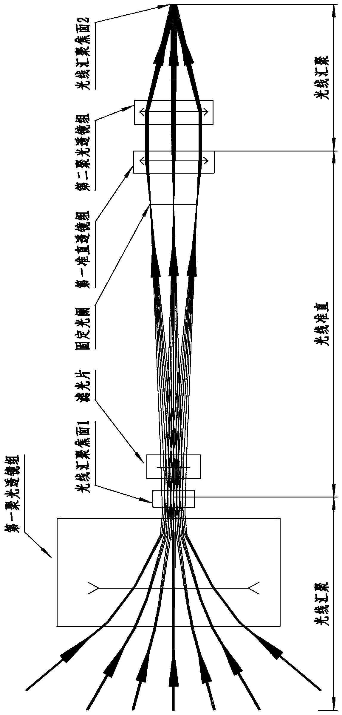
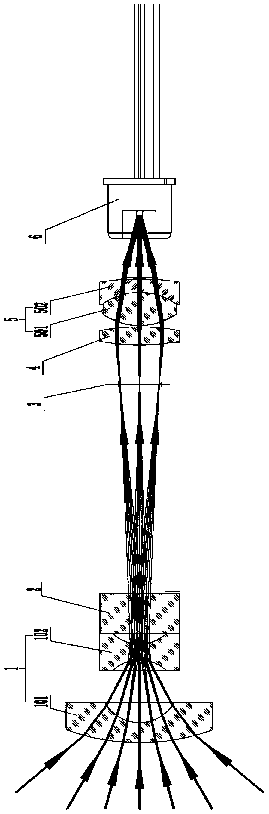
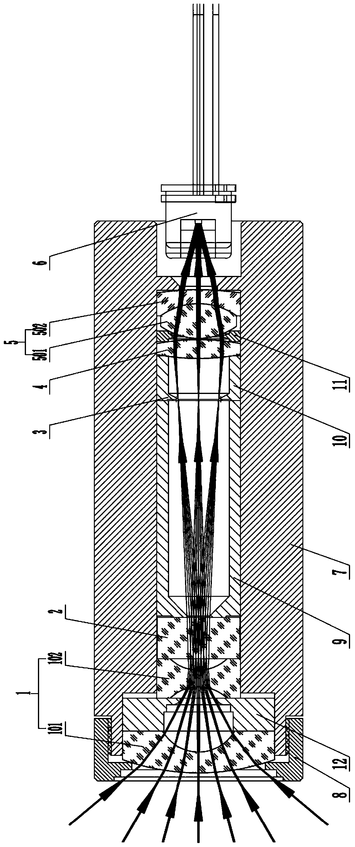
[0026] Such as Figures 1 to 3 As shown in one of them, the novel lidar receiving lens of the present invention comprises a first condenser lens group 1, an optical filter 2, a fixed diaphragm 3, a first collimator lens group 4 and a second condenser lens group arranged in sequence along the optical path. Optical lens group 5, wherein, the first condenser lens group 1 is a negative power condenser lens group, and the second condenser lens group 2 is a positive power condenser lens group, by the first condenser The optical signal received by the optical lens group 1 passes through the optical filter 2 , the fixed diaphragm 3 , the first collimating lens group 4 and the second condensing lens group 5 in sequence, and then is focused and output by the second condensing lens group 5 .

[0027] As a possible implementation form, further, the first condensing lens group 1 includes several sequentially arranged lenses, which are used to condense light signals with a large angle range...


PUM


Abstract

The invention discloses a novel laser radar receiving lens. The novel laser radar receiving lens comprises a first condensing lens group, an optical filter, a fixed diaphragm, a first collimating lensgroup and a second condensing lens group which are sequentially arranged along an optical path, wherein the first condensing lens group is a condensing lens group with negative focal power, the second condensing lens group is a condensing lens group with positive focal power, and an optical signal received by the first condensing lens group sequentially passes through the optical filter, the fixed diaphragm, the first collimating lens group and the second condensing lens group and then is focused and output by the second condensing lens group. According to the scheme, a single conventional detection unit can receive optical signals in a large view field range and can gather the optical signals in an extremely small focal plane range, so that a single consumer-level optical detector (suchas a conventional APD) can be adopted to receive optical signals in a large view field angle, namely, receive height information perpendicular to a laser radar transmitting plane. The lens group has the characteristics of the ultra-small size, the large light flux, the small distortion, the high-uniformity light spots and the low interference noise.

Description

technical field [0001] The invention belongs to the field of laser communication devices, in particular to the field of laser communication devices that can be used for unmanned vehicles, robot detection, unmanned aerial vehicle detection, automatic sweeping machines and other equipment, and specifically relates to a new type of laser radar receiving lens. Background technique [0002] Lidar is a radar that works in the optical frequency band. It uses the electromagnetic wave in the optical frequency band to first transmit a detection signal to the target, and then reflects it back to receive the same wave signal and transmit the signal for information processing, so as to obtain the position of the target (distance , azimuth and altitude), motion status (speed, attitude) and other information to realize the detection, tracking and identification of targets. Because lidar has high progress, strong anti-interference ability, simple structure and convenient use, it has been wi...

Claims


Application Information

Patent Timeline
Patent Type & Authority Applications(China)
IPC IPC(8): G02B13/00G02B13/06G01S7/481
CPCG01S7/4816G02B13/0015G02B13/0055G02B13/06
Inventor 罗联镜丁广雷肖庆红李明
Owner 福建海创光电技术股份有限公司
Why Eureka
Eureka Blog
Learn More