Femtosecond laser precision removal method for thermal barrier coating of turbine blade

A thermal barrier coating, femtosecond laser technology, applied in laser welding equipment, welding equipment, metal processing equipment, etc., can solve the problems of thermal barrier coating failure, damage, high cost, etc., and achieve the effect of high-precision removal

Inactive Publication Date: 2020-02-11
AIR FORCE UNIV PLA +1
View PDF8 Cites 10 Cited by
  • Summary
  • Abstract
  • Description
  • Claims
  • Application Information

AI Technical Summary

Problems solved by technology

However, in the actual working environment and during the coating process, it will cause partial failure and destruction of the thermal barrier coating
Due to the complex shape design and high cost of the hot end parts of the engine, the reprocessing and manufacturing costs are high, and the thermal barrier coating has good insulation and strong adhesion, the current removal methods have certain limitations

Method used


Image

  • Femtosecond laser precision removal method for thermal barrier coating of turbine blade
  • Femtosecond laser precision removal method for thermal barrier coating of turbine blade
  • Femtosecond laser precision removal method for thermal barrier coating of turbine blade

Examples


Embodiment 1

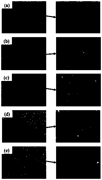
[0049] This embodiment mainly studies the influence law of laser power, and the specific process is:

[0050] The first step, before processing the workpiece, install the workpiece to be processed on the workbench, and set the parameters of the laser, among which, the wavelength is 1064nm, the pulse width is 290fs, the repetition frequency is 1000kHz, and the laser working power is 5, 10W, 15W, 20W;

[0051] The second step is to use CAD software to set the processing path, and use the laser marking control software to set specific processing conditions, where the spot diameter is 30 μm, the scanning speed is 1000 mm / s, the number of scanning times is 10, and the scanning line spacing is 0.04mm;

[0052] In the third step, when the processing starts, the ultrashort pulse laser beam is emitted from the laser source, the beam is expanded and straightened by the beam transmission adjustment system, and then reflected by the scanning galvanometer, and finally parallel focused by t...

Embodiment 2

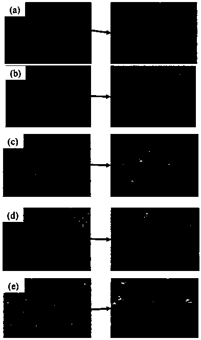
[0056] This embodiment mainly studies the influence law of the laser repetition frequency, and the specific process is:

[0057] The first step, before processing the workpiece, install the workpiece to be processed on the workbench, and set the laser parameters, among which, the wavelength is 1064nm, the pulse width is 290fs, the repetition frequency is 100KHz, 250KHz, 500KHz, 1000KHz, and the laser working power is 20W;

[0058] The second step is to use CAD software to set the processing path, and use the laser marking control software to set specific processing conditions, where the spot diameter is 30 μm, the scanning speed is 1000 mm / s, the number of scanning times is 10, and the scanning line spacing is 0.04mm;

[0059] In the third step, when the processing starts, the ultrashort pulse laser beam is emitted from the laser source, the beam is expanded and straightened by the beam transmission adjustment system, and then reflected by the scanning galvanometer, and finall...

Embodiment 3

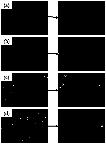
[0063] This embodiment mainly studies the influence law of the number of laser scans, and the specific process is:

[0064] The first step, before processing the workpiece, install the workpiece to be processed on the workbench, and set the parameters of the laser, among which, the wavelength is 1064nm, the pulse width is 290fs, the repetition frequency is 1000KHz, and the working power of the laser is 20W;

[0065] The second step is to use CAD software to set the processing path, and use the laser marking control software to set specific processing conditions. Among them, the diameter of the spot is 30 μm, the scanning speed is 1000 mm / s, and the number of scanning is 1, 10, and 50 times. Scanning line spacing is 0.04mm;

[0066] In the third step, when the processing starts, the ultrashort pulse laser beam is emitted from the laser source, the beam is expanded and straightened by the beam transmission adjustment system, and then reflected by the scanning galvanometer, and f...


PUM

PropertyMeasurementUnit
thicknessaaaaaaaaaa

Abstract

The invention relates to the technical field of laser machining, and discloses a femtosecond laser precision removal method for a thermal barrier coating of a turbine blade. The method mainly includesthe following steps that firstly, before a workpiece is machined, the workpiece to be machined is installed on a workbench, and corresponding parameters of a laser device are set and mainly include laser wave lengths, pulse widths, repetition frequency and laser device operating power; secondly, computer aided design (CAD) software is utilized to set a machining path, and laser marking control software is used for setting specific machining conditions comprising the scanning speed, the scanning and scanning line intervals; and thirdly, at the beginning of machining, ultrashort pulse laser beams are emitted from a laser source. According to the femtosecond laser precision removal method for the thermal barrier coating of the turbine blade, by setting performance parameters of the laser device and adjusting a light beam adjustment transmission coordination and monitoring system through a control system, high-efficiency and high-precision removal of the thermal barrier coating on a complex curved surface is realized.

Description

technical field [0001] The invention relates to the technical field of laser processing, in particular to a femtosecond laser precision removal method for a thermal barrier coating of a turbine blade. Background technique [0002] In the context of the rapid development of aviation technology, aeroengines are developing towards high flow ratio and high thrust-to-weight ratio, which largely depends on the inlet temperature of the engine turbine. The thrust-to-weight ratio of the next-generation aero-engine is greater than 12, and the service temperature of the hot-end components such as turbine blades is required to reach 2000K. With the increase of service temperature requirements for engine hot-end components, relying solely on the high-temperature resistance of superalloys can no longer meet the design requirements of aero-engines. In the past forty years, in order to meet the requirements of extreme service environments such as high-temperature shock and high-temperature...

Claims


Application Information

Patent Timeline
Patent Type & Authority Applications(China)
IPC IPC(8): B23K26/36B23K26/0622
CPCB23K26/36B23K26/0624
Inventor 周留成蔡振兵俞延庆杨家仙李玉琴王学德
Owner AIR FORCE UNIV PLA
Why Eureka
Try Eureka