Method and system for determining convective heat dissipation coefficient

A technology of heat dissipation coefficient and determination method, which is applied in the field of determination method and system of convection heat dissipation coefficient, and can solve problems such as insufficient convection heat dissipation coefficient

Active Publication Date: 2020-02-11
GUILIN UNIVERSITY OF TECHNOLOGY
View PDF13 Cites 6 Cited by
  • Summary
  • Abstract
  • Description
  • Claims
  • Application Information

AI Technical Summary

Problems solved by technology

[0003] The deficiencies of the existing technology include: (1) Simplify the complex convective heat dissipation coefficient in the friction pair braking process to a constant value that does not vary with the temperature and speed of the friction pair system; (2) Simplify the physical properties of the friction pair constituent materials to constant value for temperature change
Therefore, the rough treatment of t

Method used


Image

  • Method and system for determining convective heat dissipation coefficient
  • Method and system for determining convective heat dissipation coefficient
  • Method and system for determining convective heat dissipation coefficient

Examples


Embodiment 2

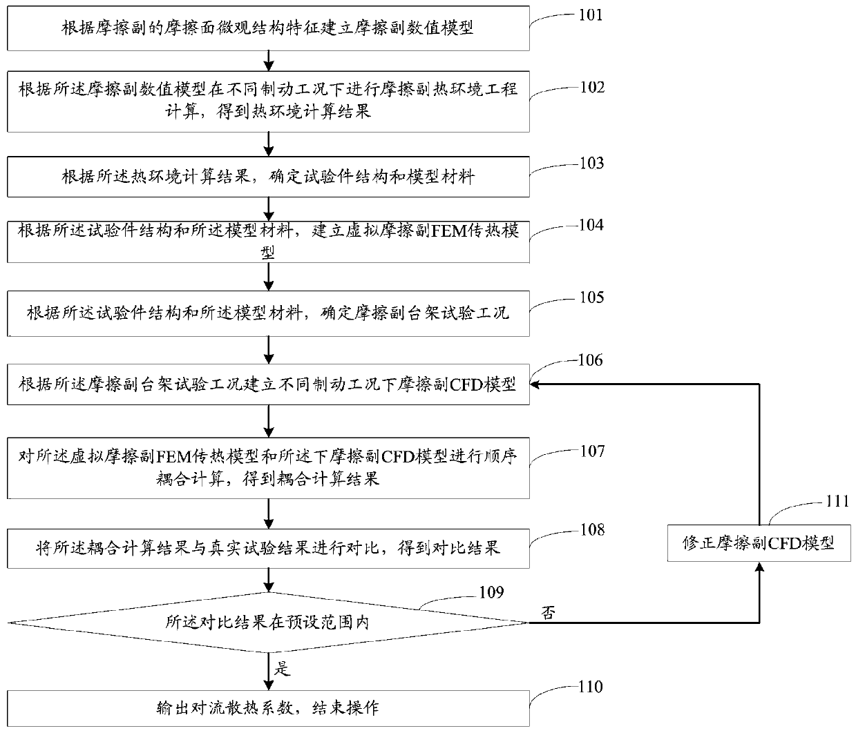
[0172] In addition to providing Embodiment 1, the present invention also provides Embodiment 2 corresponding to the technical solution of Embodiment 1. Figure 14 It is a system structure diagram for determining the convection heat dissipation coefficient of the present invention. like Figure 14 As shown, a convective heat dissipation coefficient determination system includes:

[0173] The friction pair numerical model establishment model 201 is used to establish a friction pair numerical model according to the microstructure characteristics of the friction surface of the friction pair.

[0174] The thermal environment calculation result determination module 202 is used to perform thermal environment engineering calculation of the friction pair under different braking conditions according to the friction pair numerical model, and obtain the thermal environment calculation result.

[0175] The test piece structure and model material determination module 203 is used to determ...

Embodiment 3

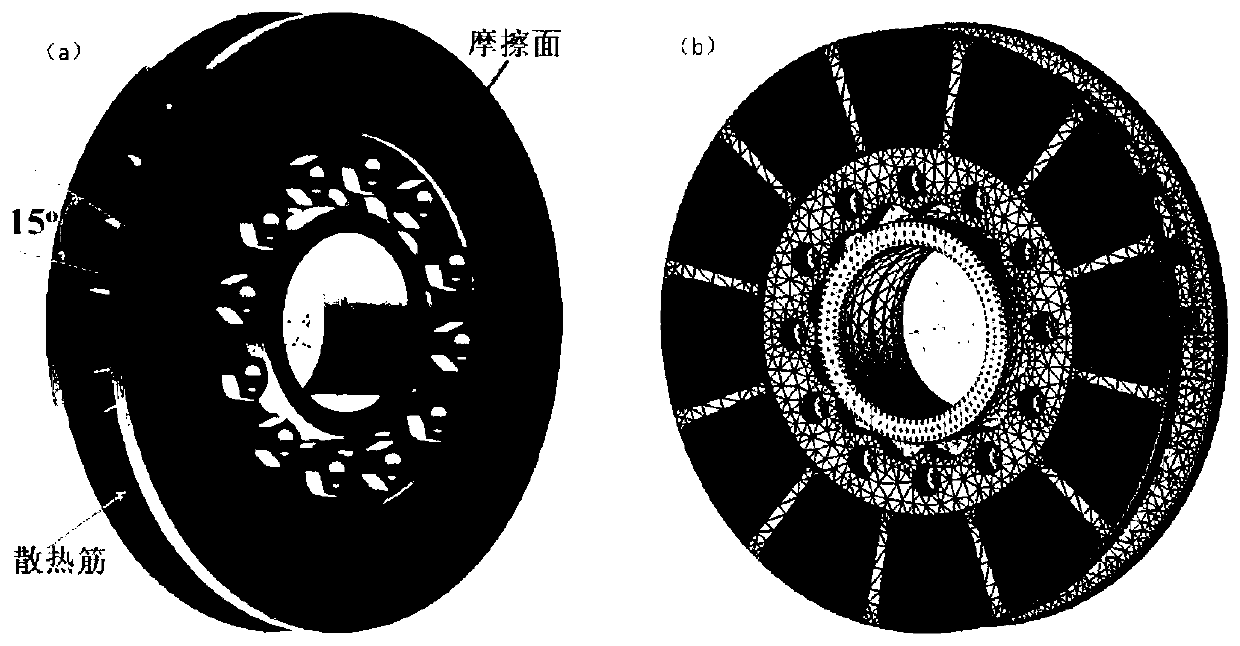
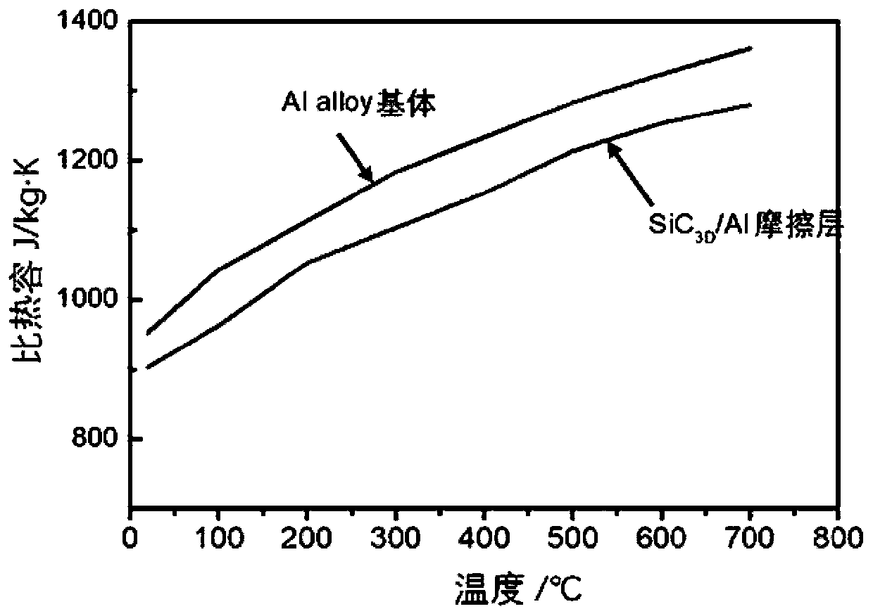
[0213] A heat-fluid-solid coupling calculation of SiC 3D The method of the friction pair of / Al composite material specifically comprises:

[0214] The finite element model of the friction pair is established with Solidworks. The disc body has 24 slat-shaped heat dissipation ribs and ventilation slots, which are symmetrically distributed on the back of the brake disc. The heat dissipation ribs are designed to be flat near the central axis to reduce the pump wind resistance torque and reduce resistance power consumption. The position of the bolt holes is simplified without affecting the calculation accuracy. The brake disc is assembled with the axle, which runs through the entire computational domain, see Figure 8 . The friction layer of the brake disc is SiC with a thickness of 5-7mm 3D / Al composite material, aluminum-silicon alloy for the rest of the disc body, physical parameters of the material. The specific heat capacity of the material changes greatly with the incr...

Embodiment 4

[0234] The invention provides a heat-fluid-solid coupling computing belt (Al 2 o 3 ) 3D The method for the automobile friction pair of / Al friction layer, comprises the steps:

[0235] Establish the numerical model of friction pair of Audi A6. The numerical model of friction pair is divided by using tetrahedral mesh and mixed mesh of hexahedron and tetrahedron. The main parameters of each component in the finite element model are the density of spokes, rims and bolt components is 7840kg / m 3 , specific heat at constant pressure is 465J / (kg K), thermal conductivity is 48W / (m K); the friction layer of the brake disc is (Al 2 o 3 ) 3D / Al composite material, the thickness of the friction layer is 3mm; the air density is 1.029kg / m 3 , the coefficient of dynamic viscosity is 2.06×10 -5 kg / (m·s), specific heat at constant pressure is 1009J / (kg·K), and thermal conductivity is 0.0296W / (m·K). The material of the friction surface composite material is calculated according to the ...


PUM

PropertyMeasurementUnit
Densityaaaaaaaaaa
Thermal conductivityaaaaaaaaaa
Thicknessaaaaaaaaaa

Abstract

The invention relates to a method and a system for determining a convective heat dissipation coefficient. The method comprises the following steps: establishing a friction pair numerical model; performing friction pair thermal environment engineering calculation under different braking conditions according to the friction pair numerical model to obtain a thermal environment calculation result; determining a test piece structure and a model material according to a thermal environment calculation result; establishing a virtual friction pair FEM heat transfer model; determining a friction pair bench test working condition; establishing a friction pair CFD model under different brake conditions according to the friction pair bench test conditions; performing sequential coupling calculation onthe virtual friction pair FEM heat transfer model and the lower friction pair CFD model to obtain a coupling calculation result; comparing the coupling calculation result with a real test result to obtain a comparison result; judging whether the comparison result is within a preset range; if yes, outputting a convective heat dissipation coefficient, and ending the operation; and if not, correctingthe CFD model of the friction pair. According to the method, the convection heat dissipation coefficient with high precision can be rapidly obtained.

Description

technical field [0001] The invention relates to the field of convective heat dissipation coefficient calculation, in particular to a method and system for determining the convective heat dissipation coefficient. Background technique [0002] As the speed of the vehicle continues to increase, the total kinetic energy continues to increase significantly, which leads to a sharp increase in the frictional heat caused by braking. The performance of the friction pair material changes under the action of high temperature, and the friction pair will produce thermal fatigue and thermal decay in the repeated braking process. At the same time, the huge frictional heat causes a significant temperature gradient, and the thermal stress caused by the temperature gradient causes cracks in the brake disc, which brings safety hazards to the braking system of vehicles and seriously threatens the safety of transportation. The braking process is a coupling process of temperature field and flow ...

Claims


Application Information

Patent Timeline
IPC IPC(8): G06F30/23G06F119/08
CPCY02T90/00
Inventor 姜艳丽夏韦美喻亮康晓安何福明
Owner GUILIN UNIVERSITY OF TECHNOLOGY
Why Eureka
Try Eureka