Millimeter wave sparse array remote monitoring imaging method and system

A sparse array and remote monitoring technology, which is applied to radio wave measurement systems, radio wave reflection/reradiation, and measurement devices, can solve the problem of high requirements for real-time signal processing hardware resources and storage resources, low computing efficiency, and computational processes. Complicated issues

Active Publication Date: 2020-02-14
博微太赫兹信息科技有限公司
View PDF8 Cites 6 Cited by
  • Summary
  • Abstract
  • Description
  • Claims
  • Application Information

AI Technical Summary

Problems solved by technology

Traditional sparse array imaging methods are generally implemented based on time-domain correlation algorithms and back-projection algorithms. The above algorithms are derived under time-domain conditions. The calculation process is relatively complicated and the calculation efficiency is low. The hardware resources and storage for real-time signal processing Resource requirements are high, therefore, a millimeter-wave sparse array remote surveillance imaging method is proposed

Method used


Image

  • Millimeter wave sparse array remote monitoring imaging method and system
  • Millimeter wave sparse array remote monitoring imaging method and system
  • Millimeter wave sparse array remote monitoring imaging method and system

Examples


Embodiment 1

[0050] This embodiment provides a technical solution: a millimeter-wave sparse array remote monitoring imaging method, including the following steps:

[0051] S1: Get the echo signal

[0052] Establish a millimeter-wave two-dimensional sparse array, and the distance between the transmitting array elements is Δx T , the distance between receiving array elements is Δy R , the transmitting array element and the receiving array element activate the corresponding antenna unit through the antenna switch. During the whole scanning process, the obtained echo signal is S(x T ,y T ,x R ,y R ,k), where x T is the emission array x dimension, y T is the emission array y-dimension, x R is the receiving array x dimension, y R is the receiving array y dimension, and k is the frequency scanning dimension;

[0053] S2: interpolation operation

[0054] For the obtained echo signal S(x T ,y T ,x R ,y R ,k) of x T dimension and y R The dimension is interpolated, and the interpolate...

Embodiment 2

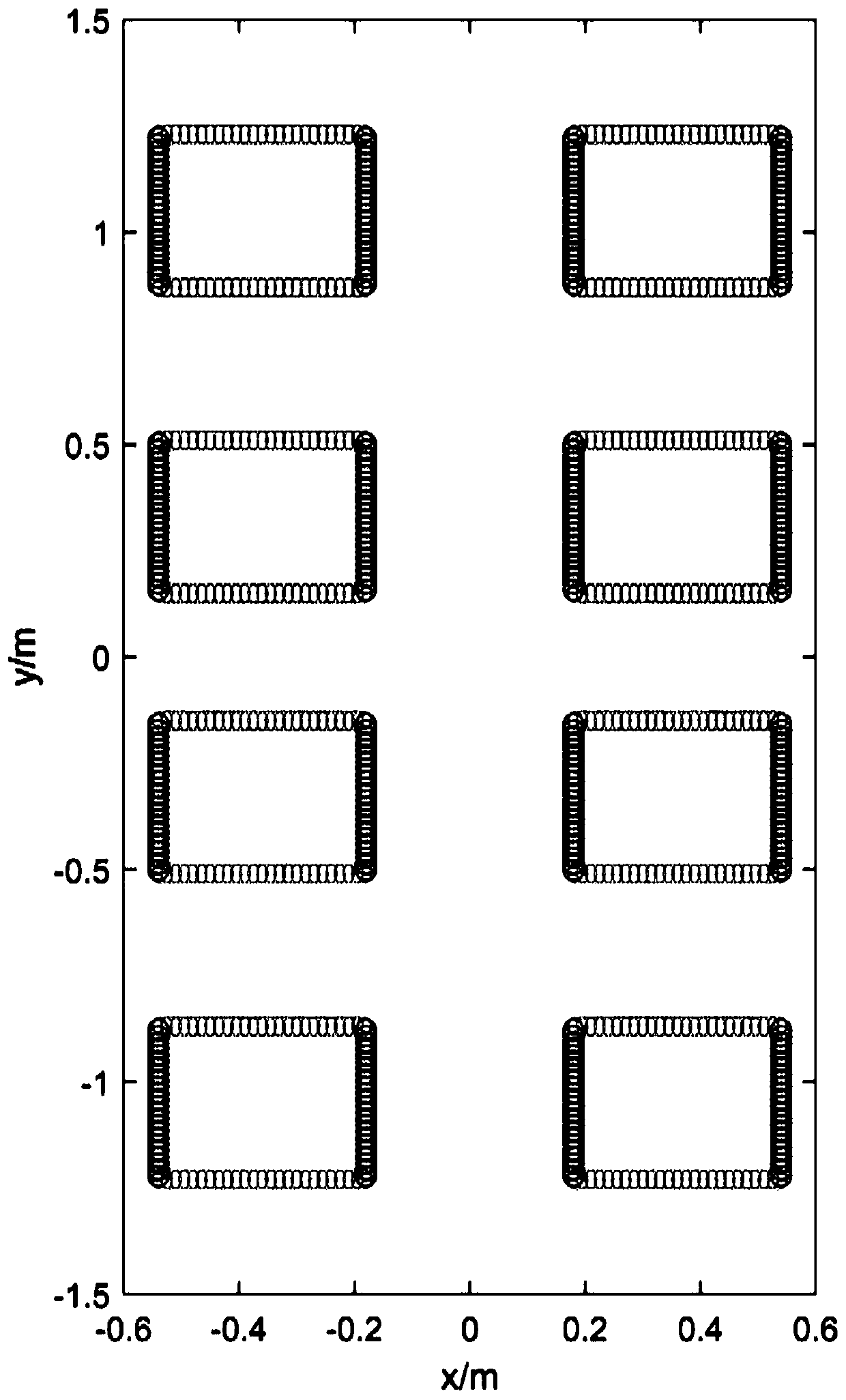
[0089] like figure 1 As shown, it is a schematic diagram of the distribution of sparse array elements of the millimeter-wave sparse array remote monitoring imaging system. Its spatial coverage is 1.08m×2.45m (azimuth dimension × vertical dimension), which can cover the entire human body, and the array elements arranged horizontally The array element arranged vertically is the receiving array element. The transmitting array element and the receiving array element realize the integration of the antenna beam in space through the switching of the antenna switch. After all the antenna switches are switched, the millimeter-wave intermediate frequency receiving The backscatter echo signal after machine demodulation is S(x T ,y T ,x R ,y R , k), x T is the emission array x dimension, y T is the emission array y-dimension, x R is the receiving array x dimension, y R is the y dimension of the receiving array, and k is the frequency scanning dimension.

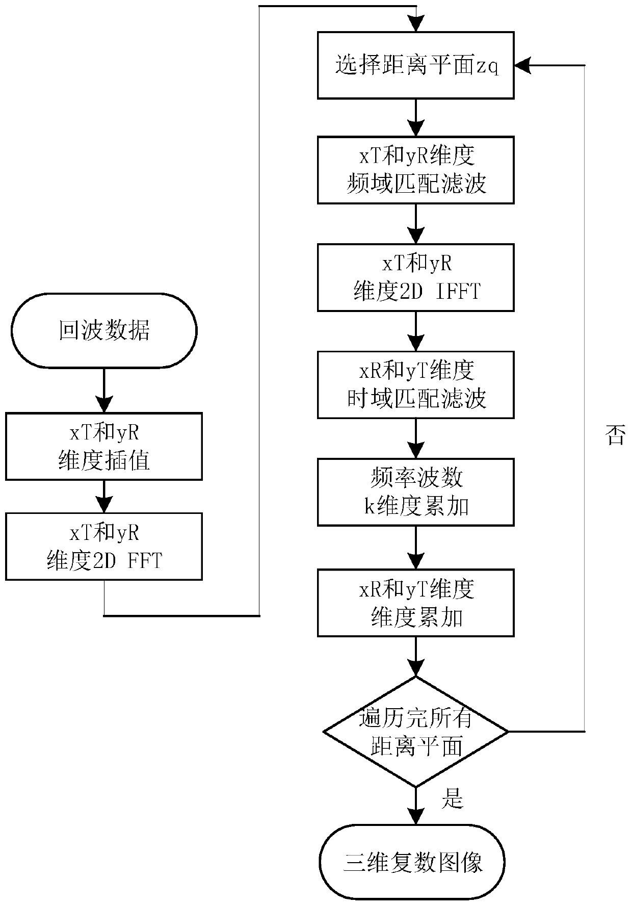
[0090] like figure 2 As...


PUM


Abstract

The invention discloses a millimeter wave sparse array remote monitoring imaging method and system, and belongs to the technical field of millimeter wave three-dimensional holographic imaging. The method comprises the following steps: S1, obtaining an echo signal; S2, performing interpolation operation; S3, performing fast Fourier transform; S4, selecting a distance plane; S5, performing frequencydomain matched filtering; S6, performing fast Fourier inverse transform; S7, performing time domain matched filtering; S8, performing coherent accumulation; and S9, obtaining a three-dimensional complex image. According to the millimeter wave sparse array remote monitoring imaging method and system disclosed by the invention, a millimeter wave sparse array full-electronic scanning imaging systemis adopted, and compared with a traditional optical machine scanning far-field imaging system, the millimeter wave sparse array full-electronic scanning imaging system has the characteristics of smallelectromagnetic wave flicker effect, high image signal-to-noise ratio and large imaging field range; meanwhile, compared with a traditional time domain type imaging method, the adopted signal processing imaging method has the advantages of less hardware resources and less storage space, the algorithm process is simple and easy to understand, the algorithm main body only comprises the main body process of fast Fourier transform, matched filtering and coherent accumulation, and the calculation efficiency is higher than that of the traditional time domain type algorithm.

Description

technical field [0001] The invention relates to the technical field of millimeter-wave three-dimensional holographic imaging, in particular to a millimeter-wave sparse array remote monitoring imaging method and system. Background technique [0002] In recent years, millimeter-wave 3D holographic imaging technology has been more and more widely used in the field of personal security inspection, which greatly reduces the workload of security personnel. It can be applied to customs, airports, courts and large-scale security activities. It is a kind of Safe, civilized and efficient new security check mode. However, the current human body security detectors based on millimeter wave technology require the security personnel to stand inside the security detector in a fixed posture, and need to stay for a short time for scanning and imaging. The imaging distance is generally very short, so the current millimeter-wave human body security detector cannot really meet the new requireme...

Claims


Application Information

Patent Timeline
Patent Type & Authority Applications(China)
IPC IPC(8): G01V8/10G01S13/04G01S7/41
CPCG01S7/41G01S13/04G01V8/10
Inventor 孟祥新郭柳柳余开张军
Owner 博微太赫兹信息科技有限公司
Why Eureka
Try Eureka