External scaffold wall connecting structure and construction method

A construction method and technology of load-bearing beams, which are applied in the direction of building structure support, building structure support, building structure support scaffolding, etc., can solve problems such as hindering construction personnel from walking, increasing demolition difficulty, relying on tower cranes, etc., to achieve control of hidden dangers of water seepage and water quality , Avoid the risk of water seepage and water leakage, and reduce the effect of repair work

Active Publication Date: 2020-02-18
广西途辉建筑工程有限公司
View PDF5 Cites 6 Cited by
  • Summary
  • Abstract
  • Description
  • Claims
  • Application Information

AI Technical Summary

Problems solved by technology

[0003] In the traditional construction of erecting cantilever beams, the steel beams must penetrate the outer wall of the building, extend into the room and lay on the floor of the main structure, and then use several U-shaped embedded parts to anchor on the floor slab and floor beams However, this method has the following disadvantages: (1) The layout of the shaped steel beams extending into the room is complicated, which hinders the cleaning of indoor construction waste and the walking of construction workers; when the shaped steel passes through the wall, it is easy to damage the concrete beams and slab components, and it is easy to cause water seepage and leakage on the floor ; Before removing the shaped steel beam, it may be necessary to cut the U-shaped anchor ring on site. After the removal, it is necessary to fill holes and subsidize bricks, which increases the construction time
(2) The fixed length of the traditional cantilevered I-beam extending into the room should not be less than 1.25 times that of the outdoor cantilever section, so under normal circumstances, it is necessary to use a steel beam ≥ 3 meters, and the steel beam at the corner needs 4 ~5 meters, there are the following disadvantages: a lot of steel is invested at one time,

Method used


Image

  • External scaffold wall connecting structure and construction method
  • External scaffold wall connecting structure and construction method
  • External scaffold wall connecting structure and construction method

Examples


Embodiment 1

[0032] In combination with the present invention Figure 1-4 The present invention is described in further detail;

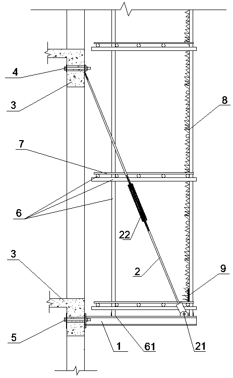
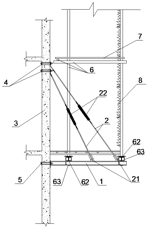
[0033] The flower basket cantilevered section steel load-bearing beam structure and construction method include the following construction steps:

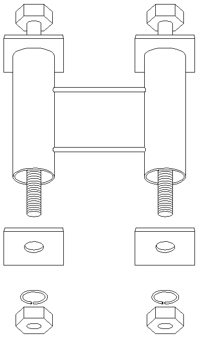
[0034] A. According to the requirements of the drawing, pre-embed the tie rod bolt casing and the cantilever bolt casing in the building exterior wall 3, and carry out concrete pouring;

[0035] B. After the pouring of the external wall 3 of the building is completed, lift the cantilevered steel beam 1 and align it with the installation hole and place it. Insert the cantilever bolt assembly 5 into the sleeve and pass through the installation hole of the cantilevered steel beam and tighten it. Tighten the rod bolt assembly 4 Fix the pull rod 2 after fixing, and the other end of the pull rod 2 is fixed on the hanging ear 21 of the cantilevered steel beam 1;

[0036] C. Adjust the turnbuckle screw 22 to tighten the ti...


PUM


Abstract

The invention discloses an external scaffold wall connecting structure and a construction method. A cantilever steel beam is fixed through bolts pre-buried in a concrete outer wall, and additionally,a basket pull rod is additionally arranged to provide lifting pull force for the cantilever steel beam. According to the external scaffold wall connecting structure, the cantilever beam does not needto stretch into a building to be fixed and is directly fixed to the outer side of the building outer wall, and the interior of the building is not affected; and after construction is completed and thecantilever beam needs to be dismounted, fire cutting is not needed, building and brushing are not needed, and the hidden danger of water seepage and leakage of a floor or a wall face is avoided.

Description

technical field [0001] The invention relates to the field of building construction, in particular to a flower basket cantilevered steel bearing beam structure and a construction method. Background technique [0002] Not both ends are supported, one end is buried or poured on the support, and the other end protrudes out of the support is called a cantilever beam. When setting up scaffolding, it is often encountered that the scaffolding is erected from the half-height of the outer wall of the building. At this time, it is necessary to set a cantilever beam on the building, and the cantilevered end of the cantilever beam protrudes out of the building. The scaffolding is gradually erected upwards from the cantilever beam as the foundation. The cantilever beam is used as the foundation and will bear a large bending stress. [0003] In the traditional construction of erecting cantilever beams, the steel beams must penetrate the outer wall of the building, extend into the room and...

Claims


Application Information

Patent Timeline
IPC IPC(8): E04G3/20E04G5/06E04G5/16E04G5/00E04G5/08E04G5/14E04G3/18E04G5/04
CPCE04G3/20E04G5/061E04G5/16E04G5/00E04G5/08E04G5/14E04G5/006E04G3/18E04G5/001E04G5/046
Inventor 饶明和
Owner 广西途辉建筑工程有限公司
Why Eureka
Try Eureka