Broadband controllable photon millimeter wave noise signal generator and signal generation method thereof

A noise signal and millimeter wave technology, applied in the field of communication, can solve the problem that the noise generator is difficult to meet the power level, and achieve the effect of real-time controllable output, flatter noise spectrum and flat noise spectrum

Active Publication Date: 2020-02-28
GUANGDONG UNIV OF TECH
View PDF9 Cites 11 Cited by
  • Summary
  • Abstract
  • Description
  • Claims
  • Application Information

AI Technical Summary

Problems solved by technology

[0007] The present invention provides a broadband controllable photonic millimeter wave noise signal generator and its signal generation method to solve the problem that existing noise generators are difficult to meet the power required by current radars and communication devices.

Method used


Image

  • Broadband controllable photon millimeter wave noise signal generator and signal generation method thereof

Examples


Embodiment 1

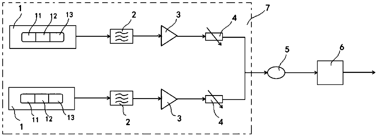
[0025] Such as figure 1 As shown, a broadband controllable photonic millimeter-wave noise signal generator includes two sets of identical chaotic light generating devices 7 (located respectively at figure 1 upper and lower sides), optical coupler 5 and photon mixer 6, the output end of each set of chaotic light generating device 7 is respectively connected to two input ends of optical coupler 5, and the output end of said optical coupler 5 is connected to photon The input end of the mixer 6, the output end of the photon mixer 6 is used as the output end of the photonic millimeter wave noise signal generator; wherein the output of two sets of chaotic light generating devices 7 is respectively two beams with different center frequencies Chaotic light with a Gaussian spectrum.

[0026] Wherein, the chaotic light generating device 7 specifically includes a three-zone integrated laser 1, an optical filter 2, an optical amplifier 3 and an optical attenuator 4, the output end of the...

Embodiment 2

[0032] This embodiment 2 is a photon millimeter wave noise signal generation method based on the photon millimeter wave noise signal generator in embodiment 1. The three-zone integrated laser 1 in the two sets of chaotic light generating devices 7 respectively output two Gaussian beams with different center frequencies. spectrum of chaotic light, the chaotic light respectively enters the filter for filtering and shaping, the filter outputs the chaotic light conforming to the standard Gaussian distribution, and the chaotic light conforming to the standard Gaussian distribution is input into the optical amplifier 3 for amplification and enters the The optical attenuator 4 is used to control its optical signal power through the optical attenuator 4, and the outputs of the two optical attenuators 4 all enter the optical coupler 5 for beat frequency processing, and the beat frequency of the output of the optical coupler 5 The signal enters the photonic mixer 6 to convert the spectru...


PUM


Abstract

The invention discloses a broadband controllable photon millimeter wave noise signal generator and a signal generation method thereof. A hyperspectral density chaotic laser is used as a photo-generated millimeter wave noise of an entropy source, high-power and broadband-adjustable millimeter wave noise is generated, compared with an existing millimeter wave noise generator, the electron bandwidthbottleneck is broken through, the generated noise bandwidth is wider, the power is higher, the noise spectrum is flatter, and the super-noise ratio is adjustable in a large range. Test requirement ofa to-be-tested device of which the upper limit of the working frequency reaches 325GHz can be met; and through combination of the optical amplifier and the optical attenuator, the optical power of thetwo paths of chaotic light can be regulated and controlled, so that real-time controllable output of millimeter wave noise power is realized. According to the invention, the problem that the existingnoise generator is difficult to meet the power required by the existing radar, communication device and the like is solved.

Description

technical field [0001] The invention relates to the field of communication technology, in particular to a broadband controllable photonic millimeter wave noise signal generator and a signal generating method thereof. Background technique [0002] Millimeter waves usually refer to electromagnetic waves with wavelengths from 10mm to 1mm and frequencies from 30GHz to 300GHz. Because millimeter waves have the advantages of large bandwidth, high transmission quality, and all-weather communication, they have broad application prospects in communication, radar, transportation, medical and other fields. . [0003] Since noise is a common source of interference in communication, radar and other fields, noise figure measurement plays an important role in the field of millimeter wave measurement. By inputting accurate and known noise to the device, module or system under test, the device can be tested The performance and ability of measuring communication equipment to receive weak sig...

Claims


Application Information

Patent Timeline
Patent Type & Authority Applications(China)
IPC IPC(8): G01R1/28G01H17/00G01S7/40H04B10/50H04B10/70
CPCG01H17/00G01R1/28G01S7/40H04B10/503H04B10/70
Inventor 孙粤辉王安帮高震森王云才王驿宣
Owner GUANGDONG UNIV OF TECH
Why Eureka
Try Eureka