
Solid waste heat insulation device for outer surface of surrounding rock of roadway and a construction process thereof

A heat insulation device and outer surface technology, which is applied in tunnels, tunnel linings, shaft equipment, etc., can solve the problems of large heat exchange volume, uneconomical cost, and waste of energy in roadways, and achieve good heat insulation performance and support capacity. Reduce the occupation of cultivated land and achieve the effect of resource recycling

Active Publication Date: 2020-03-06
SHANDONG UNIV OF SCI & TECH
View PDF5 Cites 1 Cited by
  • Summary
  • Abstract
  • Description
  • Claims
  • Application Information

AI Technical Summary

Problems solved by technology

Miners working in a high-temperature environment for a long time will cause metabolic disorders, lower work efficiency, and even heat stroke. If workers in important positions suffer from heat stroke, it may directly lead to mine accidents.
[0005] (1) Ventilation is often used in traditional mine cooling, but it is difficult to effectively solve the mine roadway temperature. When the air volume is large, it is not cost-effective economically, and the flow of air is easy to bring up dust and pollute the environment.
[0006] (2) When the cooling method is used to cool down, due to the high temperature of the rock and the large amount of heat exchange with the roadway, a lot of energy is wasted, and the cooling effect is not very good due to a large amount of heat loss
[0007] (3) In terms of mine cooling improvement, the current heat insulation method is to directly mix some heat insulation materials into concrete and spray them on the surrounding rock of the roadway, but the heat insulation effect is greatly reduced, and the effect is average.
[0008] (4) At present, industrial alkali slag solid waste is mainly disposed of on the surface, and a large amount of alkali slag will form a "white sea" after deposition and cause pollution to the surrounding environment

Method used


Image

  • Solid waste heat insulation device for outer surface of surrounding rock of roadway and a construction process thereof
  • Solid waste heat insulation device for outer surface of surrounding rock of roadway and a construction process thereof

Examples


specific Embodiment approach

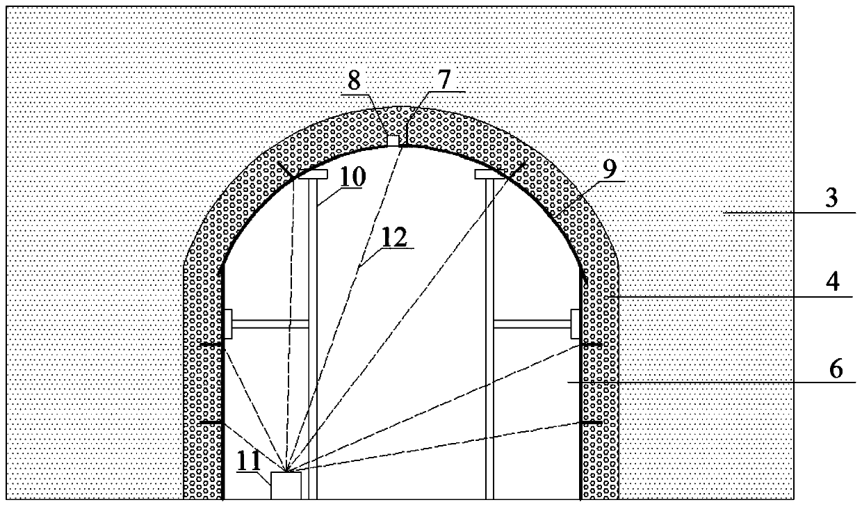
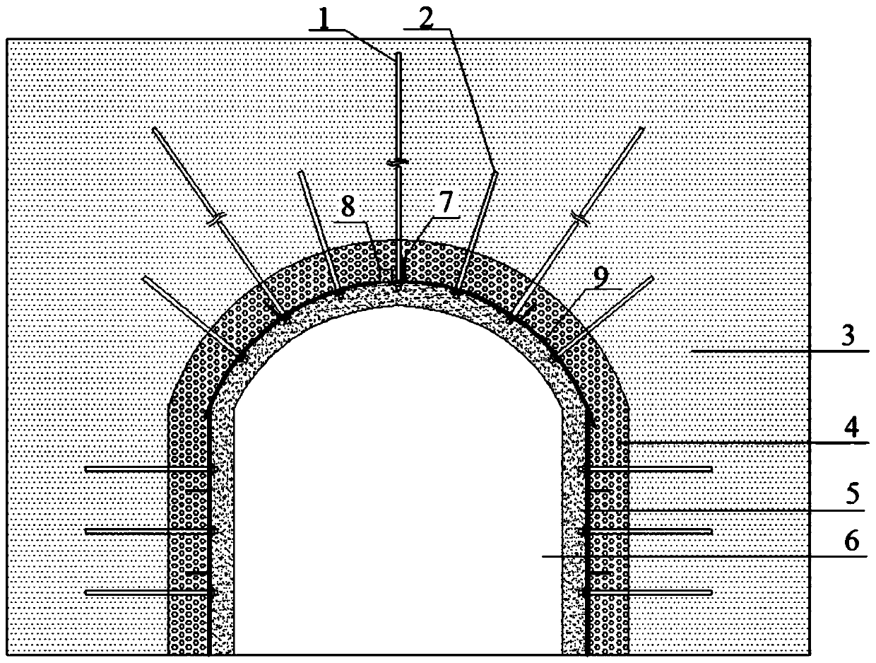
[0029] Figure 1-2 A specific embodiment of the present invention is shown: a solid waste heat insulation device for the outer surface of roadway surrounding rock includes: anchor cable 1, anchor rod 2, surrounding rock 3, solid waste heat insulation material 4, concrete layer 5, roadway 6 , silicon carbide heating rod 7, material injection port 8, corundum plate 9, temporary support device 10, variable pressure heating device 11, cable 12, the roadway 6 is arranged inside the surrounding rock 3, and the corundum plate 9 passes through the anchor cable 1, The bolt 2 is set on the outer surface of the surrounding rock 3, the solid waste heat insulation material 4 is set in the middle of the corundum plate 9 and the surrounding rock 3, the temporary support device 10 is set against the corundum plate 9, and the injection port 8 is set on the surrounding rock 3, the silicon carbide heating rod 7 is set on the surrounding rock 3, the variable pressure heating device 11 is independ...


PUM


Abstract

The invention discloses a solid waste heat insulation device for outer surface of surrounding rock of a roadway and a construction process thereof. The solid waste heat insulation device structurallycomprises an anchor cable, an anchor rod, the surrounding rock, a solid waste heat insulation material, a concrete layer, the roadway, a silicon carbide heating rod, a material injection port, a corundum plate, a temporary supporting device, a voltage transformation and temperature rise device and a cable. According to the solid waste heat insulation device, a heat insulation formwork is directlygenerated at high temperature under a well through solid waste slurry, forming is good, the heat insulation formwork is tightly combined with the surrounding rock of the roadway in shape, carrying isnot needed, solid waste is used for preparing the heat insulation formwork, solid waste emission can be reduced, and the occupied cultivated area is reduced.

Description

technical field [0001] The invention relates to the technical field of mine cooling, in particular to a solid waste heat insulation device for the outer surface of roadway surrounding rock and a construction process thereof. Background technique [0002] With the rapid development of my country's economy and society, the total volume of bulk industrial solid waste (such as alkali slag and gold tailings) has increased dramatically. Taking alkali slag as an example, alkali slag is the waste residue discharged in the process of ammonia-soda alkali production. my country's ammonia-soda alkali production can reach 4.21 million t / year. Every 1 ton of soda ash produced needs to discharge 0.3 ton of soda slag, and a factory with an annual output of 800,000 t of soda ash needs about 10 million yuan for waste slag discharge. Under normal circumstances, the alkali slag is treated by accumulating on the surface, and a large amount of alkali slag is deposited to form a "white sea", cau...

Claims


Application Information

Patent Timeline
Patent Type & Authority Applications(China)
IPC IPC(8): E21D11/38E21D11/10
CPCE21D11/10E21D11/38E21D11/381
Inventor 陈绍杰杜兆文马俊彪张振卞壮
Owner SHANDONG UNIV OF SCI & TECH
Learn More