Ultra-high-speed orthogonal polarization imaging device and method

A technology of orthogonal polarization and imaging device, which can be used in measurement devices, optical devices, microscopes, etc., and can solve the problems of sensitivity and frame rate affecting polarized light imaging systems.

Active Publication Date: 2020-03-10
JINAN UNIVERSITY
View PDF4 Cites 1 Cited by
  • Summary
  • Abstract
  • Description
  • Claims
  • Application Information

AI Technical Summary

Problems solved by technology

This mutual limitation between sensitivity and frame rate also affects almost all polarized light imaging systems

Method used


Image

  • Ultra-high-speed orthogonal polarization imaging device and method

Examples


Embodiment

[0027] The present invention is based on the time-domain widening imaging technology of dispersion Fourier transform, which has been invented and extensively researched as a high-speed microscopic imaging technology that may be applied to microscopic real-time observation.

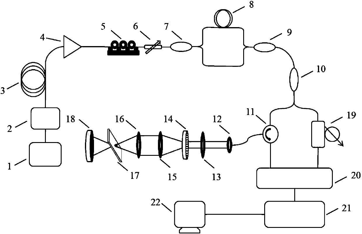
[0028] In this embodiment, as attached figure 1 As shown, a femtosecond laser ultra-high-speed orthogonal polarization imaging device based on optical coherent detection includes:

[0029]Femtosecond laser 1, filter 2, dispersion fiber 3, fiber amplifier 4, polarization controller 5 and fiber polarizer 6 connected sequentially through a single-mode fiber; polarization-maintaining coupling connected to fiber polarizer 6 through a polarization-maintaining fiber 7, the polarization maintaining coupler 7 includes two output branches, one of which is directly connected to a branch of the polarization beam combiner 9 through a polarization maintaining fiber, and the other branch is connected to the polarization ...

Embodiment 2

[0036] In this embodiment, based on the femtosecond laser ultra-high-speed orthogonal polarization imaging device based on optical coherent detection disclosed above, an ultra-high-speed orthogonal polarization imaging method is disclosed, including the following steps:

[0037] S1, femtosecond laser preprocessing steps, femtosecond laser 1 generates broadband pulsed light, filter 2 filters the laser light emitted by femtosecond laser 1, selects a central wavelength of 1550nm and a suitable spectral width, and dispersive fiber 3 pairs filtered The laser light is broadened in the time domain through the group velocity dispersion effect, and the optical fiber amplifier 4 amplifies the power of the filtered laser light after dispersion.

[0038] S2. The step of generating orthogonal double polarized light. The preprocessed laser pulse is combined with the polarization controller 5 and the fiber polarizer 6 to ensure the linear polarization state of the pulse, and then the linearly...


PUM


Abstract

The invention discloses an ultra-high-speed orthogonal polarization imaging device and method, and the imaging method comprises the following steps: carrying out filtering, dispersion, gain and orthogonal polarization multiplexing for femtosecond laser, dividing the femtosecond laser into two parts, i.e., orthogonal signal light and reference light, and enabling the orthogonal polarization direction to be along the fast and slow axes of a polarization maintaining optical fiber; enabling the signal light to be dispersed through the diffraction space, enter a spatial light imaging system, carrysample information, and return along a light path; accessing the signal light loaded with sample information and reference light to an optical coherent receiver together to complete optical coherent detection, converting the light signal into an electric signal, subjecting the electric signal to high-speed sampling and conversion through high-speed analog-to-digital conversion so as to form a digital signal to be output, and finally, demodulating and restoring an image by a computer. Compared with a traditional CCD imaging sensor, the polarization information of a sample can be obtained at anultrahigh hundred MHz frame rate under the condition that the micron-scale imaging resolution is guaranteed, and full-digital acquisition based on the optical coherent receiver is beneficial to later-period real-time analysis and image optimization processing.

Description

technical field [0001] The invention belongs to the technical field of polarization microscopy imaging, in particular to ultrafast polarization imaging technology, and more specifically to a femtosecond laser ultrahigh-speed orthogonal polarization imaging device and method based on optical coherent detection. Background technique [0002] Polarized light imaging is a very important imaging technology in the field of optical imaging, which can provide multi-dimensional information of intensity, phase and polarization. Especially in the field of biomedical imaging, polarized light imaging technology has the advantages of no invasion, low damage to samples, and sensitivity to subwavelength structural changes. The change of the light polarization state is closely related to the microstructure of the sample, so the measurement of the light polarization state can obtain rich structural information of the tissue sample. In addition to imaging static tissue structures, polarizatio...

Claims


Application Information

Patent Timeline
Patent Type & Authority Applications(China)
IPC IPC(8): G02B21/00G02B21/36G01B9/04
CPCG01B9/04G02B21/0068G02B21/0092G02B21/365
Inventor 冯元华李朝晖宋露熊松松
Owner JINAN UNIVERSITY
Why Eureka
Try Eureka