High-bonding-strength LCP substrate and preparation method

A substrate and strength technology, applied in circuit substrate materials, chemical instruments and methods, printed circuit manufacturing, etc., can solve the problems of unimproved LCP and copper foil adhesion, etc., to achieve high-frequency high-speed transmission, reduce signal loss, The effect of low dielectric loss

Inactive Publication Date: 2020-03-10
KUSN APLUS TEC CORP
View PDF9 Cites 4 Cited by
  • Summary
  • Abstract
  • Description
  • Claims
  • Application Information

AI Technical Summary

Problems solved by technology

Previous patents did not improve the adhesion between LCP and copper foil.

Method used


Image

  • High-bonding-strength LCP substrate and preparation method
  • High-bonding-strength LCP substrate and preparation method
  • High-bonding-strength LCP substrate and preparation method

Examples


Embodiment approach

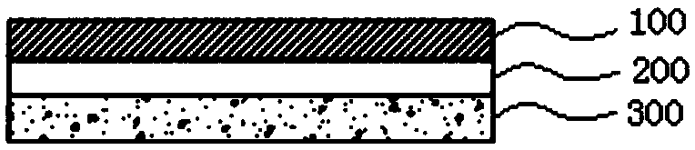
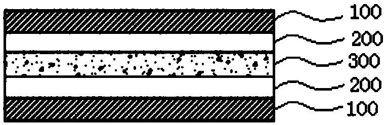
[0043] Implementation mode: a high bonding strength LCP substrate, such as Figure 1 to Figure 2 As shown, it includes at least one copper foil layer 100, at least one low dielectric adhesive layer 200, and an LCP layer 300. The low dielectric adhesive layer is located between the copper foil layer and the LCP layer and is bonded to each other. The copper foil layer and the LCP layer, the low-dielectric adhesive layer refers to a glue layer with a Dk value of 2.0-4.0 (10 GHz) and a Df value of 0.001-0.010 (10 GHz); the LCP layer refers to Dk LCP layer with a value of 2.5-4.0 (10GHz) and a Df value of 0.001-0.010 (10GHz);

[0044] The thickness of each copper foil layer is 1-35 μm; the thickness of each low-dielectric adhesive layer is 1-7 μm; the thickness of the LCP layer is 12-75 μm;

[0045] The low dielectric adhesive layer includes at least one of component A and component B, and the component A includes ceramic powder, sintered silica, Teflon, fluorine-based resin, PEEK (pol...

Embodiment approach 1

[0054] Embodiment 1: A high bonding strength LCP substrate, such as figure 1 As shown, the LCP substrate is an LCP single-sided copper foil substrate, and the LCP single-sided copper foil substrate is composed of a copper foil layer 100, a low-dielectric adhesive layer 200, and an LCP layer 300, which are sequentially from top to bottom Are the copper foil layer 100, the low dielectric adhesive layer 200 and the LCP layer 300; the thickness of the LCP single-sided copper foil substrate is 14-117 μm.

[0055] The preparation method of the LCP single-sided copper foil substrate of Embodiment 1 is as follows:

[0056] Step 1. Coat the precursor of the low dielectric adhesive layer on one side of the copper foil layer, and remove the solvent at 60-180°C;

[0057] Step 2: Coat the precursor of the LCP layer on the lower surface of the low dielectric adhesive layer, remove the solvent at 60-180°C, and then at 240-260°C (preferably 250°C), Annealing (tempering) for 8-12 hours (preferably 1...

Embodiment approach 2

[0058] Embodiment 2: A high bonding strength LCP substrate, such as figure 2 As shown, the LCP substrate is an LCP double-sided copper foil substrate, and the LCP double-sided copper foil substrate is composed of two copper foil layers 100, two low-dielectric adhesive layers 200, and an LCP layer 300, from top to bottom The thickness of the copper foil layer 100, the low dielectric adhesive layer 200, the LCP layer 300, the low dielectric adhesive layer 200, and the copper foil layer 100 in sequence; the thickness of the LCP double-sided copper foil substrate It is 16-159μm.

[0059] The preparation method of the LCP double-sided copper foil substrate of Embodiment 2 is one of the following two methods:

[0060] The first method includes the following steps:

[0061] Step 1. Coat the precursor of the low dielectric adhesive layer on one side of the copper foil layer, and remove the solvent at 60-180°C;

[0062] Step 2: Coat the precursor of the LCP layer on the surface of the low di...


PUM

PropertyMeasurementUnit
thicknessaaaaaaaaaa
thicknessaaaaaaaaaa
thicknessaaaaaaaaaa

Abstract

The invention discloses a high-bonding-strength LCP substrate, which comprises at least one copper foil layer, at least one low dielectric glue layer and an LCP layer, wherein the low dielectric gluelayer is located between the copper foil layer and the LCP layer and bonds the copper foil layer and the LCP layer; the low dielectric glue layer is a glue layer with a Dk value of 2.0-4.0 and a Df value of 0.001-0.010; the LCP layer refers to an LCP layer with a Dk value of 2.5 to 4.0 and a Df value of 0.001 to 0.010; the sum of the proportions of the component A is 0-50% (weight percentage) of the total solid content of the low dielectric glue layer; and the component B is 5-80% (weight percentage) of the total solid content of the low dielectric glue layer. According to the LCP substrate provided by the invention, the low dielectric glue layer is added between the copper foil layer and the LCP layer, and the formula and the performance of the LCP substrate are improved, so that the bonding strength between the LCP layer and the copper foil layer can be improved, the copper foil layer with a relatively low Rz value can be selected, and signal loss is not easily caused during high-frequency and high-speed transmission; in addition, the low dielectric glue layer has low dielectric constant and low dielectric loss, and is beneficial to high-frequency and high-speed transmission.

Description

Technical field [0001] The invention relates to the technical field of FPC (flexible circuit board) and its preparation, and particularly relates to an LCP substrate. Background technique [0002] Flexible boards have the advantages of continuous automated production, increased wiring density, flexibility, large design fields, three-dimensional wiring, and the ability to omit connectors and wire welding. It meets the advantages of light, thin, short and multi-functional electronic products Demand, so that the application of soft board is increasing day by day. [0003] As the demand for high-frequency and high-speed transmission increases sharply and the 5G era is approaching, the demand for high-performance engineering plastics has increased significantly. In the past, flexible copper foil substrates were made of raw materials such as copper foil and polyimide (PI) resin. High electricity, easy to absorb moisture, easy to cause signal loss under high frequency and high speed tran...

Claims


Application Information

Patent Timeline
Patent Type & Authority Applications(China)
IPC IPC(8): H05K1/03H05K1/09H05K3/02B32B15/20B32B15/04
CPCB32B15/04B32B15/20H05K1/03H05K1/0313H05K1/09H05K3/02
Inventor 李建辉杜伯贤何家华
Owner KUSN APLUS TEC CORP
Why Eureka
Try Eureka