
Tumor thermal ablation device based on non-contact power supply

A non-contact power supply and thermal ablation technology, applied in the field of biomedical electronics, can solve the problems of uneven thermal field distribution, imperfect equipment, poor controllability, etc., to achieve uniform and adjustable thermal field, convenient transmission efficiency, and reduce heat damage effect

Active Publication Date: 2020-03-17
宴晶科技(北京)有限公司
View PDF14 Cites 2 Cited by
  • Summary
  • Abstract
  • Description
  • Claims
  • Application Information

AI Technical Summary

Problems solved by technology

[0004] The ablation technology using radio frequency as the heat source occurs in the form of electric current. The conductivity and impedance of the tissue limit the ablation range. It is greatly affected by carbonization, dry tissue and heat deposition effects, and the formed thermal field is unevenly distributed and poorly controllable.
The ablation technology using microwaves as the heat source directly transmits energy to the tumor area in the form of microwave transmission, which is greatly affected by the penetration depth of the tissue. At the same time, it is easy to cause thermal damage to normal tissues outside the target area. In addition, the method is not well-equipped and the effect is unstable.

Method used


Image

  • Tumor thermal ablation device based on non-contact power supply
  • Tumor thermal ablation device based on non-contact power supply
  • Tumor thermal ablation device based on non-contact power supply

Examples


Embodiment 1

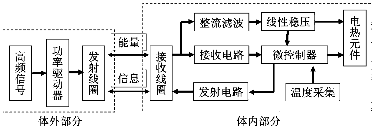
[0030] figure 1 It is a schematic structural diagram of a tumor thermal ablation device based on non-contact power supply in Example 1 of the present invention. Such as figure 1 As shown, the tumor thermal ablation device based on non-contact power supply in this embodiment includes: an electromagnetic generating device, a transmitting coil, a receiving coil and an electric heating element; the output end of the electromagnetic generating device is connected to the transmitting coil, and the The electromagnetic generating device is used to generate electromagnetic energy, and transmit the electromagnetic energy to the transmitting coil; the receiving coil is set corresponding to the transmitting coil, and is used to receive the electromagnetic energy emitted by the transmitting coil, and transmit the electromagnetic energy to the transmitting coil. The electromagnetic energy is converted into electric energy; the output end of the receiving coil is connected with the electric...

Embodiment 2

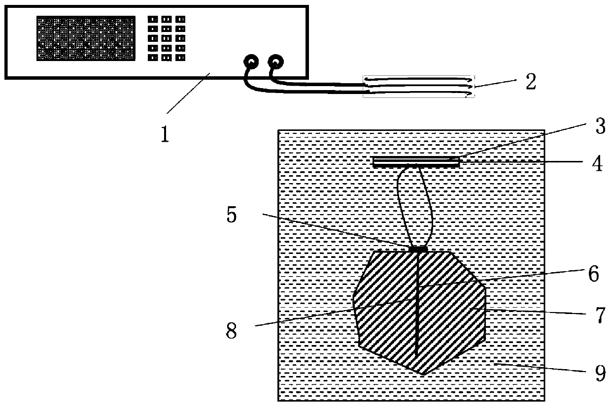
[0037] figure 2 It is a schematic diagram of a tumor thermal ablation device based on non-contact power supply in Example 2 of the present invention. Such as figure 2As shown, the tumor thermal ablation device based on non-contact power supply in this embodiment adopts non-contact power supply technology to directly introduce electric energy into the tumor tissue site, and realize thermal ablation of tumor tissue through temperature-controlled heating of the electric heating element. The tumor thermal ablation device based on non-contact power supply in this embodiment includes an external energy transmitting part and an internal energy receiving part. The external energy transmitting part includes a signal generating and power driver 1 and a transmitting coil 2. The signal generating and power driver 1 passes a high frequency signal The generator generates a high-frequency signal with modulation information, and then the power driver amplifies the power of the high-frequen...

Embodiment 3

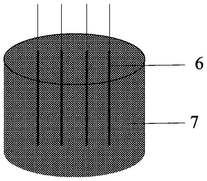
[0044] The implementation process of this embodiment is roughly the same as that of Embodiment 2. The difference is that in this embodiment, the shape of the tumor is different from that of Embodiment 2. Therefore, the layout of the heating elements in this embodiment is different from that of Embodiment 2. different. Figure 4 It is a schematic diagram of placing the electric heating element inside the tumor of the tumor thermal ablation device based on non-contact power supply in Example 3 of the present invention, as shown in Figure 4 As shown, in this embodiment, one electric heating element is placed in the tumor mass, two electric heating elements surround the tumor mass horizontally, and two electric heating elements vertically surround the tumor block to realize multi-point heating of tumor tissue, and the heating element accessories are placed in multiple points The temperature sensor measures the temperature, and controls the heating power of the electric heating el...


PUM


Abstract

The invention discloses a tumor thermal ablation device based on non-contact power supply. The tumor thermal ablation device comprises an electromagnetic generation device, a transmitting coil, a receiving coil and an electric heating element; the output end of the electromagnetic generation device is connected with the transmitting coil, and the electromagnetic generation device is used for generating electromagnetic energy and transmitting the electromagnetic energy to the transmitting coil; the receiving coil and the transmitting coil are correspondingly arranged, and the receiving coil isused for receiving electromagnetic energy transmitted by the transmitting coil and converting the electromagnetic energy into electric energy; the output end of the receiving coil is connected with the electric heating element; when tumor thermal ablation treatment is carried out, the electric heating element is arranged in a to-be-treated tumor area. According to the tumor thermal ablation devicebased on non-contact power supply, the non-contact power supply technology is adopted, electric energy is directly led into a tumor tissue part, and thermal ablation of tumor tissue is achieved through temperature control heating of the electric heating element; accurate positioning can be achieved within the minimally invasive scale, the conformability is good, a thermal field is evenly distributed and can be regulated and controlled, wounds to the human body are small, and damage to normal tissue is small.

Description

technical field [0001] The invention relates to the technical field of biomedical electronics, in particular to a tumor thermal ablation device based on non-contact power supply. Background technique [0002] Malignant tumors have the characteristics of high incidence and high recurrence rate, and have become one of the major diseases that threaten human health. Traditional tumor treatment methods include surgical resection, radiotherapy and chemotherapy. In recent years, with the rapid development of biomedical engineering technology, tumor thermal ablation technology has successfully realized the clinical application of tumor treatment, opening up a new way for tumor treatment. [0003] Tumor thermal ablation is a kind of in situ inactivation aimed at one or more specific tumor lesions in an organ or tissue, using physical methods to heat the tissue to produce biological effects, directly leading to irreversible damage or coagulation necrosis of tumor cells technology. ...

Claims


Application Information

Patent Timeline
IPC IPC(8): H02J50/20H05B3/00
CPCH05B3/0019H05B3/0085H02J50/20
Inventor 金鑫谢雪松王明连王群
Owner 宴晶科技(北京)有限公司
Learn More