
A kind of desulfurization and denitrification equipment and method

A desulfurization and denitrification equipment technology, applied in the field of desulfurization and denitrification, can solve problems affecting water source safety, sulfur dioxide and nitrogen oxide entry, environmental pollution, etc., and achieve the effects of simple operation, reduced loss, and easy adjustment

Active Publication Date: 2022-02-18
郴州万墨环保科技有限公司
View PDF4 Cites 0 Cited by
  • Summary
  • Abstract
  • Description
  • Claims
  • Application Information

AI Technical Summary

Problems solved by technology

[0002] Wastewater refers to the general term for the water discharged during residents' activities and runoff rainwater. It includes domestic sewage, industrial wastewater, and other useless water such as primary rainwater that flows into drainage pipes and channels. After pollution, it is difficult to purify water that does not meet a certain standard. In industrially developed areas of our country, sulfur dioxide and nitrogen oxides in the air are easy to enter surface wastewater due to rainfall, and will converge with water flow and enter lakes and reservoirs. Affect the safety of water sources and cause serious environmental pollution;
[0003] However, the existing desulfurization and denitrification equipment is generally aimed at the exhaust gas discharged from the factory, which can effectively reduce the sulfur dioxide and nitrogen oxides contained in the exhaust gas, but some sulfur dioxide and nitrogen oxides will still enter the air and enter with the rainfall. In surface wastewater, therefore, it is necessary to design a desulfurization and denitrification equipment and method for desulfurization and denitrification treatment of wastewater

Method used


Image

  • A kind of desulfurization and denitrification equipment and method
  • A kind of desulfurization and denitrification equipment and method
  • A kind of desulfurization and denitrification equipment and method

Examples


Embodiment 1

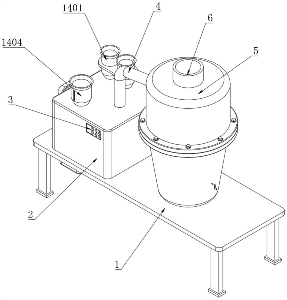
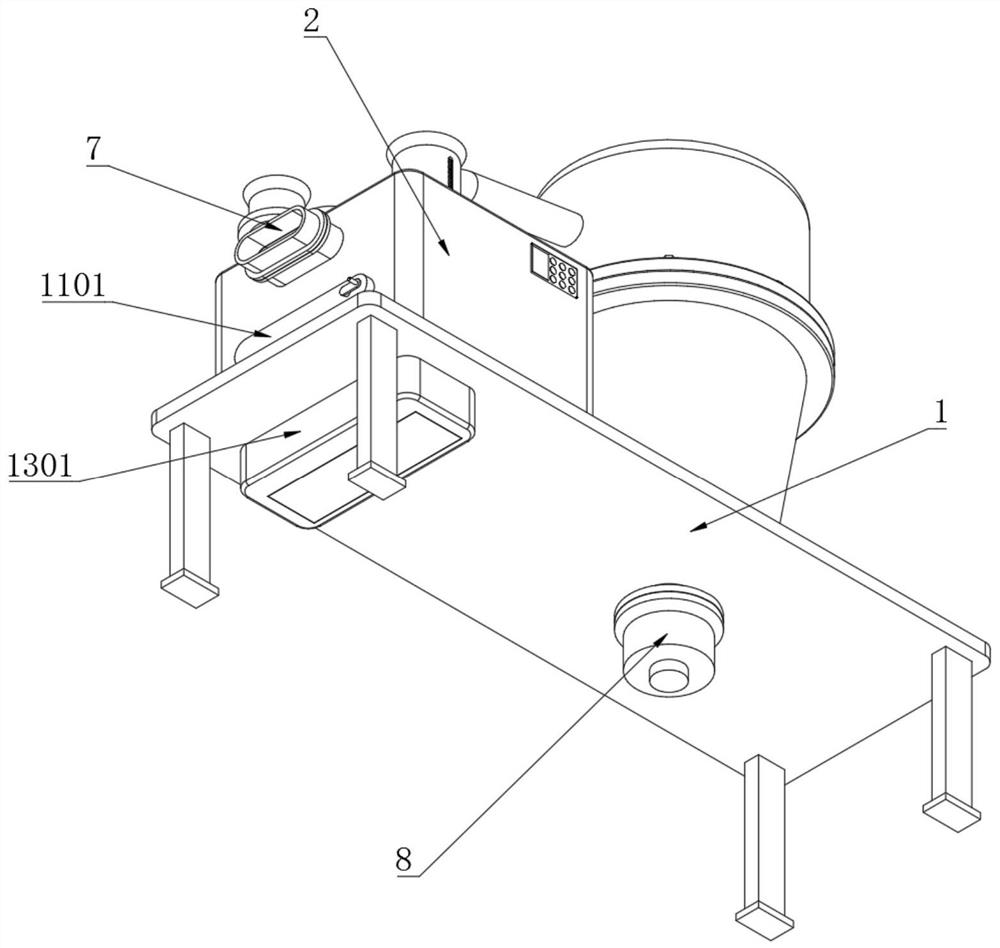
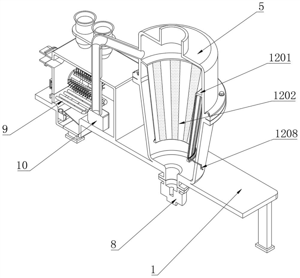
[0054] Embodiment 1: as Figure 1-11 As shown, the present invention provides a technical solution, a kind of desulfurization and denitrification equipment, including a placement rack 1, a transfer box 2 is installed on the top of the placement rack 1, a control switch 3 is embedded and connected to one end of the transfer box 2, and a control switch 3 is connected to the top of the transfer box 2. The conveying pipe 4, the top of the placement frame 1 corresponds to the position on the side of the transfer box 2, and the swirl scrubber 5 is installed through it. The top of the swirl scrubber 5 is connected to the outlet pipe 6, and the other end of the transfer box 2 is connected to the waste water inlet pipe. 7. The bottom end of the swirl scrubber 5 is connected with a sewage outlet 8, a heating pipe 9 is installed on the inner wall of one end of the transfer box 2, and a waste water extraction pump 10 is installed on the inner wall of the bottom end of the transfer box 2; ...

Embodiment 2

[0066] Embodiment 2: as Figure 12 As shown, the present invention provides a technical solution, a process for using desulfurization and denitrification equipment, which specifically includes the following steps:

[0067] S1. Wastewater heating: transfer the wastewater to be treated to the transfer box for heating;

[0068] S2. Preliminary separation: use a separation extraction pump and a separation net to separate the larger solid impurities contained in the wastewater;

[0069] S3, adding reactant: adding sodium sulfide, ammonium chloride and ammonia water to the heated wastewater;

[0070] S4. Cyclone separation: the wastewater is then transferred to the cyclone scrubber, and the solid sediment and wastewater are separated by cyclone;

[0071] S5. Discharge detection: the separated solid sediment and waste water are discharged separately, and the contents of sulfur dioxide and nitrogen oxides in the discharged waste water are detected.

[0072] According to the above t...

Embodiment 3

[0074] Embodiment 3: as Figure 12 As shown, the present invention provides a technical solution, a process for using desulfurization and denitrification equipment, which specifically includes the following steps:

[0075] S1. Wastewater heating: transfer the wastewater to be treated to the transfer box for heating;

[0076] S2. Preliminary separation: use a separation extraction pump and a separation net to separate the larger solid impurities contained in the wastewater;

[0077] S3, adding reactant: adding sodium sulfide, ammonium chloride and ammonia water to the heated wastewater;

[0078] S4. Cyclone separation: the wastewater is then transferred to the cyclone scrubber, and the solid sediment and wastewater are separated by cyclone;

[0079] S5. Discharge detection: the separated solid sediment and waste water are discharged separately, and the contents of sulfur dioxide and nitrogen oxides in the discharged waste water are detected.

[0080] According to the above t...


PUM

PropertyMeasurementUnit
pore sizeaaaaaaaaaa

Abstract

The invention discloses a desulfurization and denitrification equipment, which comprises a placement rack, a transfer box is installed on the top of the placement rack, a control switch is embedded and connected to one end of the transfer box, and a delivery pipe is connected to the top of the transfer box. A swirl scrubber is installed through the top of the rack corresponding to one side of the transfer box. The structure of the invention is scientific and reasonable, and it is safe and convenient to use. It can be shaken and shaken through the set crank handle, rotating shaft, transmission gear, transmission tooth chain and cleaning bristles. Brush the stains attached to the surface of the heating tube to avoid excessive stains on the surface of the heating tube and affect the heating effect. Through the set adjustment handle, adjustment gear, sliding mounting plate and driven tooth groove, the adjustment handle can be shaken to drive The connecting baffle moves to block the meshes of the filter, thereby adjusting the use of the meshes of the filter, facilitating the adjustment of the filtering effect of the filter, the alternate use of the meshes of the filter, and reducing the loss of the filter.

Description

technical field [0001] The invention relates to the technical field of desulfurization and denitrification, in particular to a desulfurization and denitrification equipment and method. Background technique [0002] Wastewater refers to the general term for the water discharged during residents' activities and runoff rainwater. It includes domestic sewage, industrial wastewater, and other useless water such as primary rainwater that flows into drainage pipes and channels. After pollution, it is difficult to purify water that does not meet a certain standard. In industrially developed areas of our country, sulfur dioxide and nitrogen oxides in the air are easy to enter surface wastewater due to rainfall, and will converge with water flow and enter lakes and reservoirs. Affect the safety of water sources and cause serious environmental pollution; [0003] However, the existing desulfurization and denitrification equipment is generally aimed at the exhaust gas discharged from t...

Claims


Application Information

Patent Timeline
Patent Type & Authority Patents(China)
IPC IPC(8): C02F9/04C02F101/10C02F101/16
CPCC02F9/00C02F1/001C02F1/38C02F1/00C02F2303/14C02F2101/101C02F2101/16
Inventor 欧传高许林忠
Owner 郴州万墨环保科技有限公司
Learn More