Electronic equipment integrated with millimeter wave array antenna

A millimeter-wave antenna and electronic equipment technology, applied in the field of mobile communication, can solve the problems of easy occlusion, coexistence of metallized body, etc., and achieve the effects of small impedance impact, simple processing, and small signal loss

Pending Publication Date: 2020-03-27
天通瑞宏科技有限公司
View PDF0 Cites 14 Cited by
  • Summary
  • Abstract
  • Description
  • Claims
  • Application Information

AI Technical Summary

Problems solved by technology

[0003] In the terminal equipment, the conventional millimeter wave antenna directly integrates the radiating element into the back end of the RF chip stack, integrates with the chip, and sets it on the main printed circuit board (PCB), but its radiation direction can only be towards the back of the terminal equipment. , easily occluded
If it is placed upright around the terminal equipment, the problem of antenna radiation directionality will be improved, but how the millimeter wave antenna coexists with 2G, 3G, 4G antennas, and how to coexist with the metalized body will bring challenges to engineering design

Method used


Image

  • Electronic equipment integrated with millimeter wave array antenna
  • Electronic equipment integrated with millimeter wave array antenna
  • Electronic equipment integrated with millimeter wave array antenna

Examples


Embodiment Construction

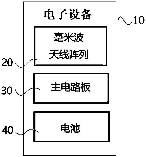
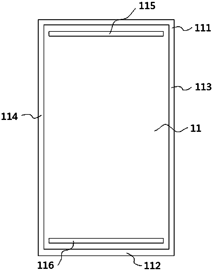
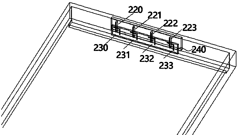
[0023] As shown in the drawings, an electronic device integrated with a millimeter wave array antenna includes a millimeter wave antenna array 20, a main printed circuit board PCB30, a battery 40, and a first metal middle frame 11, the first metal middle frame 11 includes The metal frame located on the external surface of the electronic device, the large-area metal block for supporting and grounding, the first clearance area 115 and the second clearance area 116. The metal frame includes a metal frame I 111, a metal frame II 112, a metal frame III 113, and a metal frame IV 114. The metal frame I 111 is provided with a first double-sided groove area 21, and the first double-sided groove area 21 is front and back. There are grooves on both sides with a metal partition in the middle. The first groove area 21 is used to set up a millimeter wave antenna array 20. The millimeter wave antenna array 20 is composed of more than two antenna elements and arranged in an array form.

[0024] ...


PUM


Abstract

The invention discloses electronic equipment integrated with a millimeter wave array antenna. The millimeter wave antenna comprises a millimeter wave antenna array, a main printed circuit board (PCB),a battery and a first metal middle frame, the method is characterized in that the first metal middle frame comprises a metal frame positioned on the appearance surface of the electronic equipment anda large-area metal block for supporting and grounding; the metal frames comprise a metal frame I, a metal frame II, a metal frame III and a metal frame IV; a first double-sided groove area is arranged in the metal frame I, grooves are formed in the front surface and the back surface of the first double-sided groove area, a metal partition is arranged in the middle of the first double-sided groovearea, the first groove area is used for arranging a millimeter wave antenna array, and the millimeter wave antenna array consists of more than two antenna units and is arranged in an array form. According to the invention, the optimal radiation direction of the millimeter wave array antenna can be realized, performance degradation caused by shielding of the millimeter wave array antenna by surrounding devices or the environment when consumers use the millimeter wave array antenna is avoided, the feeding and grounding realization mode is simple, and the realization cost is low.

Description

Technical field [0001] The invention relates to the field of mobile communication, and in particular to an electronic device integrating a millimeter wave array antenna. Background technique [0002] At present, commercial 5G (fifth generation mobile communications) will be implemented around 2020, including the Sub 6GHz frequency band and millimeter wave (millimeter wave) frequency band. Millimeter wave refers to electromagnetic waves with a wavelength of millimeter level and a frequency of 30 to 300 GHz. It has the advantages of large bandwidth and large channel capacity, and can better meet the needs of 5G communications for large data traffic. At present, the research and development of phased array beamforming in the 5G sub-6Ghz MIMO technology and millimeter wave frequency band in smart terminal equipment has attracted people's attention. [0003] In the terminal equipment, the conventional millimeter wave antenna integrates the radiating element directly into the back end o...

Claims


Application Information

Patent Timeline
Patent Type & Authority Applications(China)
IPC IPC(8): H01Q1/24H01Q1/36H01Q1/48H01Q1/50H01Q13/10H01Q21/00H01Q21/08
CPCH01Q1/243H01Q1/36H01Q1/48H01Q1/50H01Q13/10H01Q21/00H01Q21/08
Inventor 朱德进王婕綦超张伟刘石桂
Owner 天通瑞宏科技有限公司
Why Eureka
Try Eureka