GTAW welding system and method suitable for ultra-narrow gap

A welding system and gap technology, used in welding equipment, welding accessories, arc welding equipment, etc., can solve the problems of difficult to guarantee the stability of the welding process, sensitive arc characteristics, and arc welding wire burnback, etc. Small heat input, the effect of reducing the processing area

Active Publication Date: 2020-04-10
SHANDONG UNIV
View PDF2 Cites 3 Cited by
  • Summary
  • Abstract
  • Description
  • Claims
  • Application Information

AI Technical Summary

Problems solved by technology

However, with the further reduction of the groove width, the arc characteristics become more sensitive, the arc is unstable, and it is easy for the arc to climb on the side wall, burn on the side wall and burn back the welding wire
At present,

Method used


Image

  • GTAW welding system and method suitable for ultra-narrow gap
  • GTAW welding system and method suitable for ultra-narrow gap
  • GTAW welding system and method suitable for ultra-narrow gap

Examples


Embodiment 1

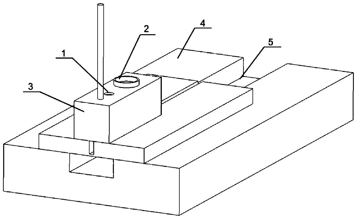
[0057] A GTAW welding system suitable for ultra-narrow gaps, including argon arc welding power supply, TIG welding torch, welding trolley, wire feeding device, and gas protection device.

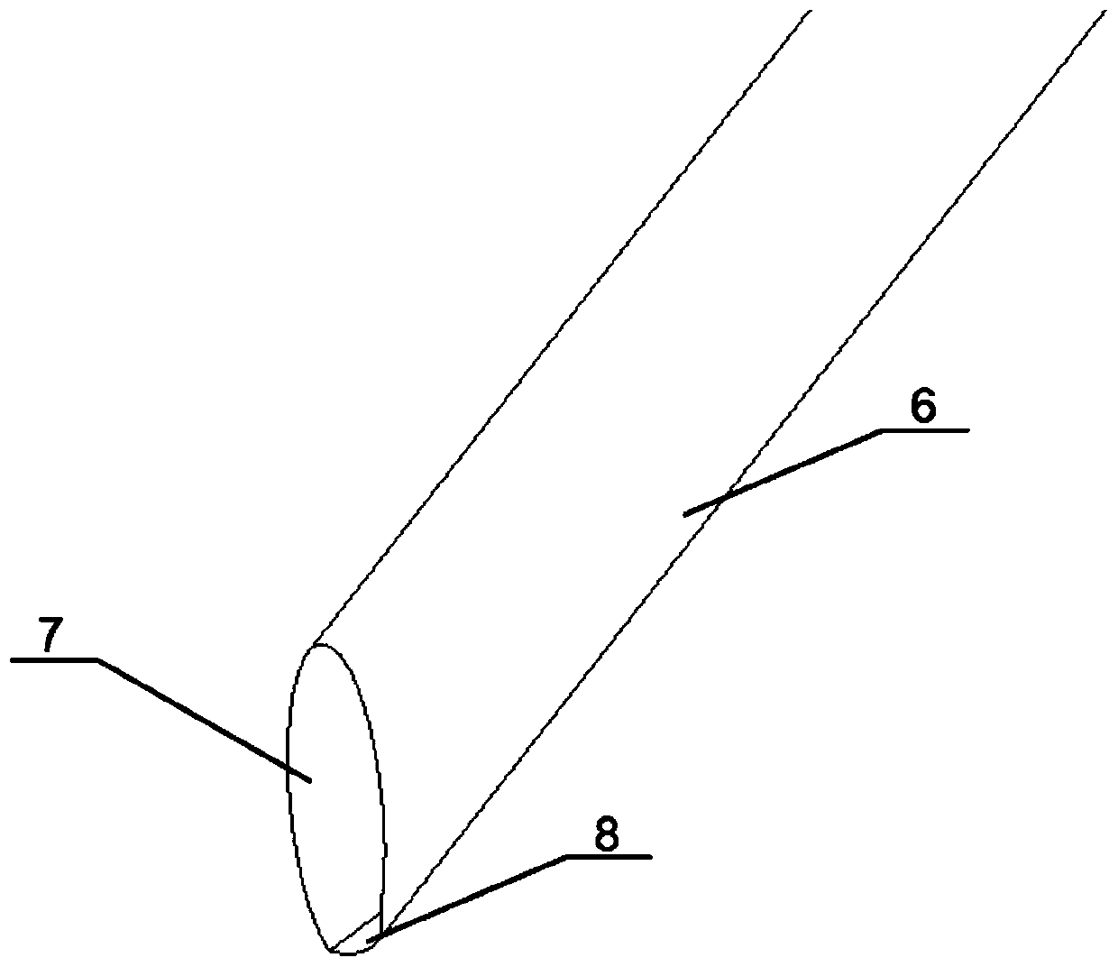
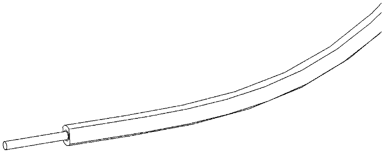
[0058] TIG welding torch includes torch shell, rotating motor, central rotating shaft, rotating tungsten pole, conductive system, and air supply system. The rotating motor is connected to the rotating tungsten pole through the central rotating shaft, and the rotating tungsten pole is non-axisymmetric. The argon arc welding power supply is connected and provides power, and the gas supply system is used to provide shielding gas to the welding torch; the rotating tungsten pole is driven to rotate periodically by a rotating motor.

[0059] The TIG welding torch is fixed on the welding trolley, and the TIG welding torch is driven by the welding trolley to move.

[0060] The wire feeding device is mechanically connected with the TIG welding torch and moves synchronously with the welding torch; the...

Embodiment 2

[0066] A GTAW welding system suitable for ultra-narrow gaps, its structure is as described in Embodiment 1, the difference is that the TIG welding torch is fixedly connected to the welding trolley through threaded bolts. The distance between the welding torch and the workpiece in the horizontal direction and the vertical height direction can be adjusted by adjusting the screw thread.

Embodiment 3

[0068] A GTAW welding system suitable for ultra-narrow gaps, its structure is as described in Embodiment 1, the difference is that the end of the central rotating shaft is tightly threaded with the rotating tungsten pole through anti-wire. On the one hand, it ensures good air tightness, and on the other hand, it ensures that the thread becomes tighter and tighter during the rotation process. During welding, the shielding gas circulates in the body of the torch to accelerate the heat dissipation of the central rotating shaft, the rotating tungsten pole and the conductive copper block.


PUM


Abstract

The invention relates to a GTAW welding system and method suitable for an ultra-narrow gap, and belongs to the technical field of narrow gap welding. The system comprises an argon arc welding power supply, a TIG welding gun, a welding trolley, a wire feeding device and a gas protection device; the TIG welding gun comprises a rotating motor, a rotating tungsten electrode, a conductive system and anair supply system; the rotating motor drives the rotating tungsten electrode to rotate through a central rotating shaft, the rotating tungsten electrode is a non-axisymmetric tungsten electrode, theconductive system is used for being connected with an argon arc welding power source and providing electric power, and the air supply system is used for providing shielding gas for the interior of thewelding gun; the TIG welding gun is fixedly arranged on the welding trolley and is driven by the welding trolley to move; the wire feeding device and the welding gun synchronously move; the gas protection device is a shell and covers a workpiece to be welded. The system can be suitable for ultra-narrow gaps with the gaps being less than 6 mm, electric arcs are stably combusted in the welding process, the side wall is effectively fused, heat input can be reduced, and the system is suitable for all-position welding and high in practicability.

Description

technical field [0001] The invention relates to a GTAW welding system and a welding method suitable for ultra-narrow gaps, belonging to the technical field of narrow gap welding. Background technique [0002] Narrow gap welding technology is a method to realize high-efficiency and high-quality welding of thick plates by using fully automatic welding equipment and arc control technology in narrow gap grooves. Narrow-gap welding technology is usually used in the welding of low-alloy steel thick-walled vessels and some important alloy components. Compared with the traditional groove, the cross-sectional area of ​​the groove is reduced by more than 50%, which effectively reduces the consumption cost of welding filler materials, and can reduce the welding level, thereby effectively reducing the welding stress and deformation of the workpiece. [0003] On the basis of the narrow gap welding technology, the ultra-narrow gap welding technology has been gradually developed by furthe...

Claims


Application Information

Patent Timeline
IPC IPC(8): B23K9/167B23K9/133B23K9/12B23K9/32
CPCB23K9/125B23K9/133B23K9/167B23K9/32B23K9/325
Inventor 贾传宝吴玮魏斌周继辉
Owner SHANDONG UNIV
Why Eureka
Try Eureka