
Anaerobic flow biofilm reactor

A flow biological and membrane reactor technology, applied in anaerobic digestion treatment, biological water/sewage treatment, chemical instruments and methods, etc., can solve the problems of poor mixing effect of sewage and carrier, affecting microbial degradation, trouble, etc. The flow direction is stable, the decomposition is complete, and the effect of reducing stacking

Active Publication Date: 2022-02-18
浙江永续环境工程有限公司
View PDF29 Cites 0 Cited by
  • Summary
  • Abstract
  • Description
  • Claims
  • Application Information

AI Technical Summary

Problems solved by technology

[0004] When the above-mentioned reactor is used for water treatment, the sewage enters from the original water supply pipe at the bottom, and the sewage enters the UASB reactor and then flows upward. However, during this process, the sewage is mixed by flowing through the solid fiber packing Pall ring, which may easily cause the sewage to be mixed with the carrier. The mixing effect is not good, and it is easy to affect the degradation of pollutants in sewage by microorganisms, which is troublesome and needs to be improved

Method used


Image

  • Anaerobic flow biofilm reactor
  • Anaerobic flow biofilm reactor
  • Anaerobic flow biofilm reactor

Examples


Embodiment 1

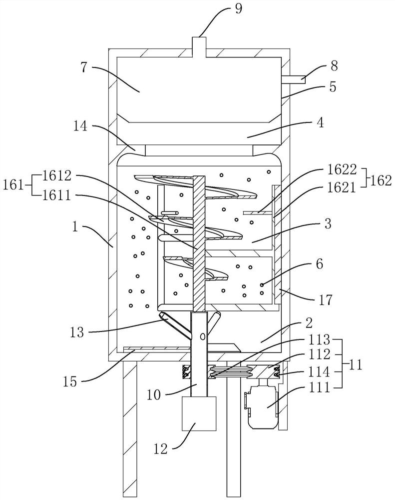
[0035] An anaerobic flow biofilm reactor, such as figure 1 As shown, a cylindrical reaction box 1 is included, and the axis of the reaction box 1 is vertically arranged. The reaction box 1 includes a water inlet area 2 , a reaction area 3 , a precipitation area 4 and a water outlet area 5 connected from bottom to top. The reaction zone 3 is provided with a small granular filler carrier 6, and the filler carrier 6 can usually be quartz sand, anthracite, activated carbon, ceramsite or zeolite and the like. A three-phase separator 7 is provided in the water outlet area 5, and the three-phase separator 7 is inserted into the precipitation area 4 to be set. Going out of the reaction box 1, the top of the three-phase separator 7 is provided with an exhaust pipe 9, and the exhaust pipe 9 is passed through the reaction box 1 and fixed on the top of the reaction box 1. This type is all existing settings, and will not be described here. Do repeat.

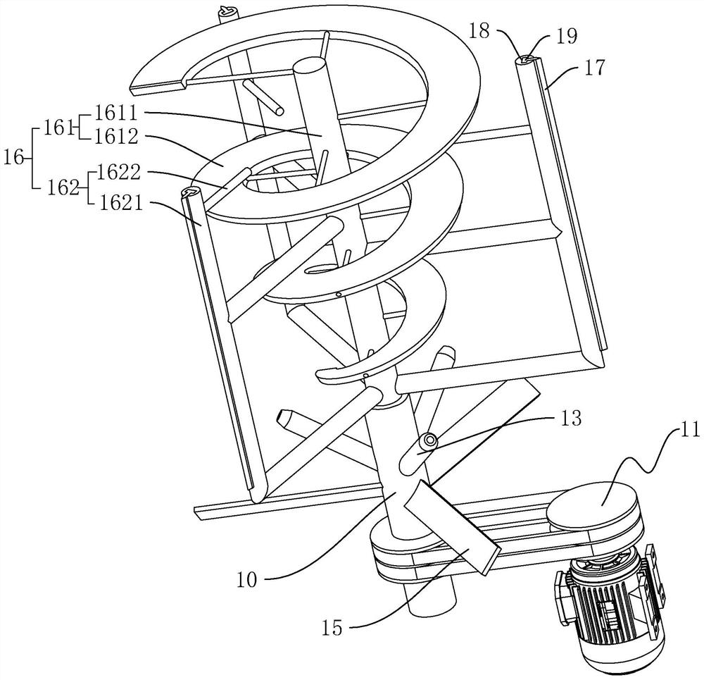
[0036]The bottom of the reaction b...

Embodiment 2

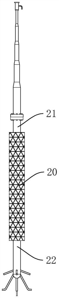
[0044] An anaerobic flow biofilm reactor, the difference between the second embodiment and the first embodiment is that it also includes a shell 20, the shell 20 is in the shape of a mesh cover, the upper end of the shell 20 is connected with a water inlet 21, and the shell 20 The lower end is provided with a water outlet 22. The reaction box 1 (not shown in the figure) is located in the casing 20, and the water inlet pipe 10 (not shown in the figure) is connected to the water inlet 21, and the water outlet 8 (not shown in the figure) is connected to the water outlet 22 set up.


PUM


Abstract

The invention discloses an anaerobic flow biofilm reactor, which relates to the field of sewage treatment. The main points of the technical solution are: a cylindrical reaction box, which includes a water inlet area, a reaction area, a sedimentation area and a water outlet area , a three-phase separator is installed in the water outlet area, and the three-phase separator is inserted into the sedimentation area to set up. The reaction area is equipped with a filler carrier, and the bottom of the reaction tank is connected to a water inlet pipe. A drive assembly is provided; one end of the water inlet pipe located in the reaction tank is evenly connected with a number of water outlet rods along the circumference, and each water outlet rod is inclined upward in a direction away from the axis of the water inlet pipe; a baffle ring is provided near the reaction area near the sedimentation area , the end face of the baffle ring close to the water inlet area is arranged obliquely downward towards the axis close to the reaction box. The water outlet rod and the baffle ring are set, so that the mixing effect of the filler carrier and the sewage is also better, and the pollutants in the sewage are degraded more thoroughly.

Description

technical field [0001] The invention relates to the field of sewage treatment, more specifically, it relates to an anaerobic flow biofilm reactor. Background technique [0002] The flow biofilm reactor is an improved new composite biofilm reactor developed on the basis of fixed bed reactors, fluidized bed reactors and biofilters. It overcomes the need for regular backwashing in fixed bed reactors, the need to fluidize the carrier in fluidized bed reactors, and the complex operations of cleaning filter materials and replacing aerators in submerged biofilters, and retains the traditional biofilm It has the characteristics of anti-shock load, less sludge output and long sludge age. The main principle is to use the sewage to continuously flow through the reactor packing carrier to form a biofilm on the carrier, and the microorganisms multiply and grow on the biofilm. The biofilm grows on the smaller carrier unit, and the carrier moves freely with the water flow in the reactor ...

Claims


Application Information

Patent Timeline
Patent Type & Authority Patents(China)
IPC IPC(8): C02F3/28
CPCC02F3/2853
Inventor 言红红郑言郑勇生
Owner 浙江永续环境工程有限公司
Learn More