Transfer printing method and application

A technology of transfer printing and graphic layer, applied in the direction of copying/marking method, printing, etc., can solve the problems of high adhesion coefficient between the interface between two substrates and graphic layer, inability of graphic layer to be damaged, peeling, etc.

Active Publication Date: 2020-04-14
INST OF FLEXIBLE ELECTRONICS TECH OF THU ZHEJIANG +1
View PDF4 Cites 0 Cited by
  • Summary
  • Abstract
  • Description
  • Claims
  • Application Information

AI Technical Summary

Problems solved by technology

However, these traditional transfer printing technologies have high requirements for the adhesion coefficient between the interface of the two substrates and the graphic layer, and the graphic layer is easily damaged during the transfer process, so it cannot be quickly and completely transferred from the interface of the transfer substrate. peel off

Method used


Image

  • Transfer printing method and application
  • Transfer printing method and application
  • Transfer printing method and application

Examples


preparation example Construction

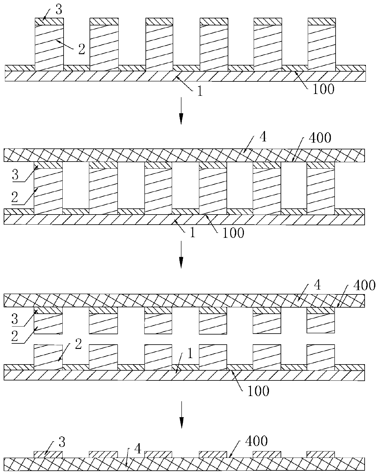
[0042] In the preparation method provided by the present invention, the liquid metal is formed on the first surface 100 of the first substrate 1 to form the pre-patterned layer 2, and the pre-patterned layer 2 includes the oxide of the liquid metal formed on the surface of the liquid metal. Wherein, the interfacial binding force between the liquid metal and the first surface 100 of the first substrate 1 is relatively small, so it can be easily transferred or separated from the first substrate 1; the oxide of the liquid metal and the oxide formed on The graphic layers 3 on the prefabricated graphic layer 2 can be connected by chemical bonds, thus having a strong bonding force; and the adhesive force between the graphic layer 3 and the second substrate 4 is greater than that between the liquid metal and the first Interfacial bonding force between substrates 1. In this way, during the separation process of the first substrate 1 and the second substrate 4, the prefabricated patter...

Embodiment 1

[0087] Place the gallium indium alloy in an oxygen-enriched environment for 30s and stir it, and use it as a raw material to print on the surface of the magnesium alloy substrate by 3D printing to form a prefabricated pattern layer. In the prefabricated pattern layer, the oxide of the gallium indium alloy and the The mass ratio of gallium-indium alloy is approximately 1:200, that is, only a small amount of gallium-indium alloy is controlled to undergo oxidation reaction.

[0088] The thickness of the prefabricated pattern layer is approximately 10 μm, and the gold particles are deposited on the surface of the prefabricated pattern layer by magnetron sputtering to form a pattern layer, and the thickness of the pattern layer is 10 nm;

[0089] The magnesium alloy substrate with the patterned layer deposited is taken out from the deposition chamber, and the polyimide substrate is pasted on the surface of the patterned layer deposited on the magnesium alloy substrate, and then the ...

Embodiment 2

[0093] Put the gallium indium tin alloy in the air for 30 minutes and stir it, and use it as a raw material to form a prefabricated pattern layer by spraying on the surface of the polydimethylsiloxane base, and the oxidation of the gallium indium tin alloy in the prefabricated pattern layer The mass ratio of the compound to the gallium indium tin alloy is 1:50;

[0094] The thickness of the prefabricated pattern layer is 200 μm, and titanium oxide is deposited on the surface of the prefabricated pattern layer by chemical vapor deposition to form a pattern layer, and the thickness of the pattern layer is 100 μm;

[0095] The polydimethylsiloxane substrate with the pattern layer deposited is taken out from the deposition chamber, and the polyethylene terephthalate substrate is pasted on the surface of the polydimethylsiloxane substrate deposition pattern layer side, and then provided intercalation agent, and separate the polydimethylsiloxane substrate and the polyethylene tereph...


PUM

PropertyMeasurementUnit
thicknessaaaaaaaaaa
thicknessaaaaaaaaaa
thicknessaaaaaaaaaa

Abstract

The invention provides a transfer printing method. The method comprises the following steps of providing liquid metal, and forming a prefabricated pattern layer on a first substrate by the liquid metal; providing a functional material to make the functional material form a pattern layer on a surface of the prefabricated pattern layer; providing a second substrate, attaching the second substrate tothe pattern layer, separating the first substrate from the second substrate, and transferring the pattern layer to the second substrate to obtain a prefabricated body; and providing an etching solution, and removing the residual prefabricated pattern layer on the prefabricated body by the etching solution to obtain a second substrate transferred with the pattern layer. The invention also providesa functional device manufactured by the transfer printing method. In the invention, the liquid metal which is a low-viscosity substance is used as a transfer printing medium so that a transfer printing structure is not limited by viscosity or a surface binding force of a surface material, and transfer printing can be quickly and completely performed between two surfaces.

Description

technical field [0001] The invention relates to the technical field of transfer printing, in particular to a transfer printing method and its application. Background technique [0002] Transfer printing technology is the key technology to realize the transfer of graphics layer from one substrate to another substrate. Traditional transfer printing technologies include: transfer printing based on rate correlation, transfer printing based on microstructure, transfer printing based on load regulation, laser Driven transfer printing and transfer printing based on shape memory polymers, etc. However, these traditional transfer printing technologies have high requirements for the adhesion coefficient between the interface of the two substrates and the graphic layer, and the graphic layer is easily damaged during the transfer process, so it cannot be quickly and completely transferred from the interface of the transfer substrate. peel off. Contents of the invention [0003] In v...

Claims


Application Information

Patent Timeline
Patent Type & Authority Applications(China)
IPC IPC(8): B41M5/382
CPCB41M5/382
Inventor 冯雪张柏诚刘兰兰付浩然蒋晔
Owner INST OF FLEXIBLE ELECTRONICS TECH OF THU ZHEJIANG
Why Eureka
Try Eureka