
Gas inlet and exhaust safety system of liquefied gas bottle and using method

A safety system and technology for liquefied gas cylinders, which are applied in the field of air intake and exhaust safety of liquefied gas cylinders, and can solve the problems of liquefied gas cylinders bulging, explosion, and vehicle bottle expansion.

Inactive Publication Date: 2020-04-14
WUHU HAIGE RUIDE SCI & TECH
View PDF4 Cites 3 Cited by
  • Summary
  • Abstract
  • Description
  • Claims
  • Application Information

AI Technical Summary

Problems solved by technology

The liquefied gas cylinder is a bottle for storing liquefied gas. This kind of vehicle bottle is used to store and infuse liquefied gas for long-distance trucks. There are liquid inlet pipelines and gas supply pipelines, but in the process of long-distance driving, it is difficult to avoid the vaporization of the liquefied petroleum gas inside the car bottle, which makes the internal pressure of the car bottle boost, because the conventional method cannot achieve self-exhaust, and then The internal expansion of the vehicle bottle will cause the liquefied gas cylinder to bulge or explode, and when the liquefied gas inside the liquefied gas cylinder is used too much, the pressure inside the bottle will decrease, making it difficult for the liquefied gas to come out of the liquefied gas cylinder

Method used


Image

  • Gas inlet and exhaust safety system of liquefied gas bottle and using method
  • Gas inlet and exhaust safety system of liquefied gas bottle and using method
  • Gas inlet and exhaust safety system of liquefied gas bottle and using method

Examples


Embodiment Construction

[0046] The technical solutions of the present invention will be further described below in conjunction with the accompanying drawings and through specific implementation methods.

[0047] Wherein, the accompanying drawings are only for illustrative purposes, showing only schematic diagrams, rather than physical drawings, and should not be construed as limitations on this patent; in order to better illustrate the embodiments of the present invention, some parts of the accompanying drawings will be omitted, Enlarged or reduced, does not represent actual product size.

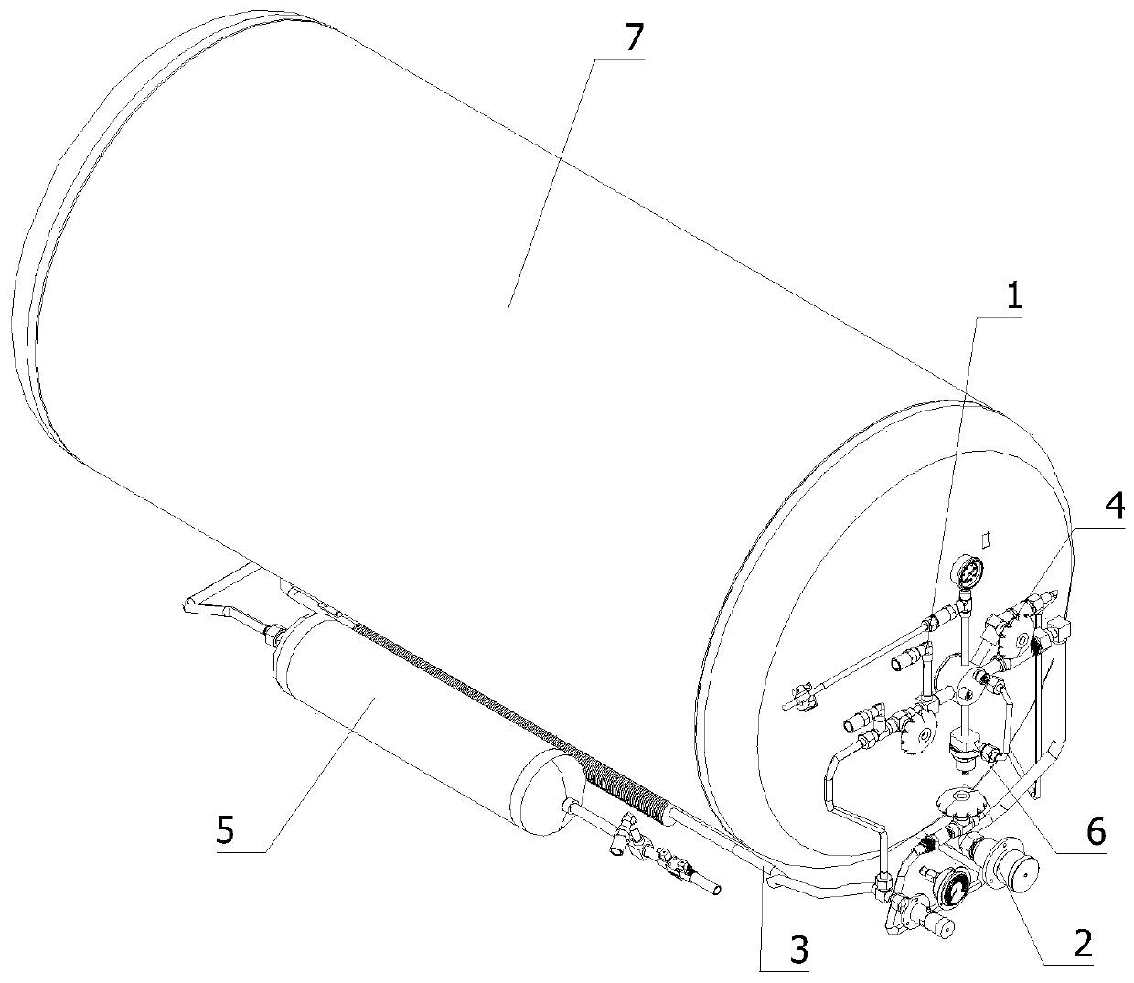
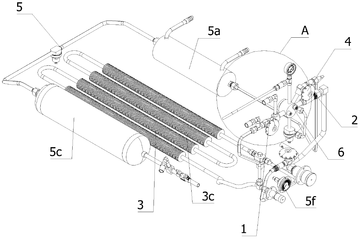
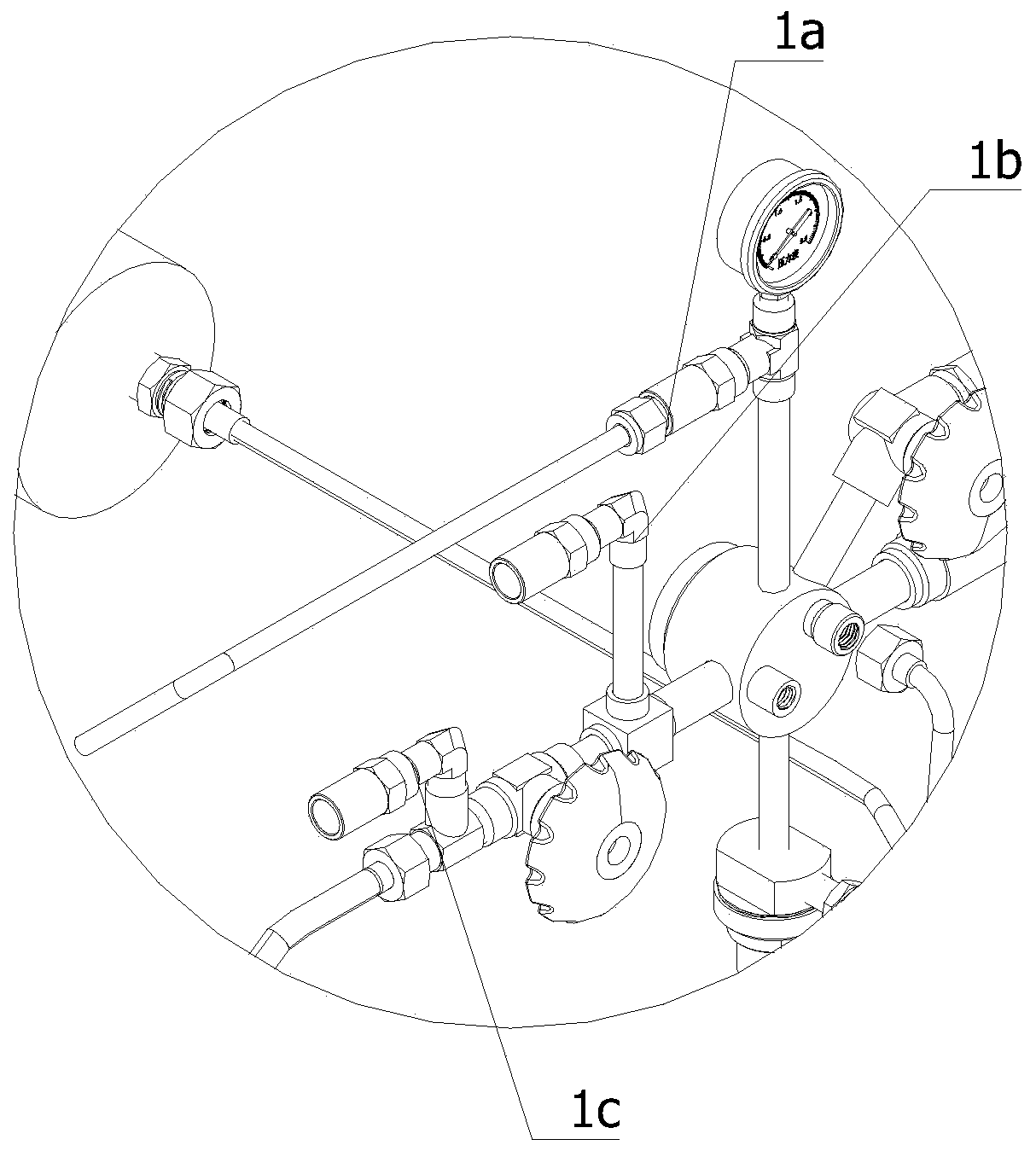
[0048] refer to Figure 1 to Figure 9 The air intake and exhaust safety system of a liquefied gas cylinder shown includes a safety valve assembly 1, a liquid inlet pipeline 2, a self-pressurization pipeline 3, a liquid outlet pipeline 4, a gas supply pipeline 5, and an economical pipeline 6 and the tank body 7, the air inlet of the safety valve assembly 1 is connected with the liquid outlet of the tank body 7, th...


PUM


Abstract

The invention relates to the gas inlet and exhaust safety field of a liquefied gas bottle and especially relates to a gas inlet and exhaust safety system of the liquefied gas bottle and a using method. The system comprises a safety valve assembly, a liquid inlet pipeline, a self-pressurization pipeline, a liquid outlet pipeline, a gas supply pipeline, an economic pipeline and a tank body. An air inlet of the safety valve assembly is connected with a liquid outlet of the tank body. An air outlet of the air supply pipeline is connected with an air inlet of an automobile engine. By using the liquefied gas bottle, when a liquefied gas in a vehicle bottle is vaporized, under effects of a self-pressurization pipe safety valve assembly and the economic pipeline, the liquefied gas in the liquefiedgas bottle is released and used, pressure in the liquefied gas bottle is ensured, internal expansion of the liquefied gas bottle is avoided, and bulging or explosion of the liquefied gas bottle is avoided too. When the liquefied gas in the liquefied gas bottle is used too much, the pressure in the bottle is reduced, and the liquefied gas is vaporized through the self-pressurization pipeline so that the internal pressure of the liquefied gas bottle is increased, and the liquefied gas can be discharged from the liquefied gas bottle conveniently.

Description

technical field [0001] The invention relates to the field of air intake and exhaust safety of liquefied gas cylinders, in particular to an air intake and exhaust safety system of liquefied gas cylinders and a use method. Background technique [0002] Liquefied petroleum gas, also known as liquefied petroleum gas, is a colorless volatile liquid obtained by liquefying natural gas or petroleum under pressure and cooling. It is highly prone to spontaneous combustion. When its content in the air reaches a certain concentration range, it can explode when it encounters an open flame. The liquefied petroleum gas obtained through the refinery is mainly composed of one or two of propane, propylene, butane, and butene, and it is also doped with a small amount of pentane, pentene, and a small amount of sulfide impurities. If the liquefied petroleum gas is to be further purified, an alcohol amine absorption tower can be used to absorb and remove the carbon dioxide sulfide, and finally t...

Claims


Application Information

Patent Timeline
IPC IPC(8): F17C5/02F17C7/04F17C13/04F17C13/12F17D1/02B60K15/03B60K15/035F02M21/02
CPCB60K15/03006B60K15/035B60K2015/03019B60K2015/03375F02M21/0215F02M21/0287F17C5/02F17C7/04F17C13/04F17C13/123F17C2223/0153F17C2225/0123F17C2227/04F17C2270/0171F17D1/02Y02T10/30
Inventor 肖则名
Owner WUHU HAIGE RUIDE SCI & TECH
Learn More