
A high-efficiency solar-blind ultraviolet light transmitter and receiver system

A receiver and ultraviolet light technology, applied in the field of solar blind ultraviolet light detection, can solve the problems of solar blind ultraviolet light insensitivity, time-consuming operation, large volume, etc., achieve optical path and structural design optimization, improve reliability, and small size Effect

Active Publication Date: 2021-01-12
NANJING UNIV OF POSTS & TELECOMM
View PDF4 Cites 0 Cited by
  • Summary
  • Abstract
  • Description
  • Claims
  • Application Information

AI Technical Summary

Problems solved by technology

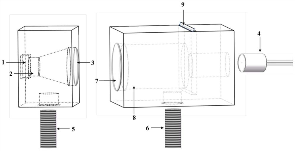
[0006] In order to solve the problems in the prior art that the detector is not sensitive to solar-blind ultraviolet light, and the existing solar-blind ultraviolet light signal receiving and sending devices in the laboratory are large in size, easy to loosen, and time-consuming to operate, the present invention provides a high-efficiency solar-blind ultraviolet light Ultraviolet light emission and receiver system, the system optimizes the light propagation path, and can use solar-blind ultraviolet detectors to directly detect solar-blind ultraviolet light; it can also use light conversion materials with detectors to detect indirectly

Method used


Image

  • A high-efficiency solar-blind ultraviolet light transmitter and receiver system
  • A high-efficiency solar-blind ultraviolet light transmitter and receiver system
  • A high-efficiency solar-blind ultraviolet light transmitter and receiver system

Examples


Embodiment 1

[0048] This embodiment is used to demonstrate the use of the present invention to directly detect solar-blind ultraviolet light, using a 278 nm LED as a light source; the photodetector inside the receiver uses an ultraviolet PIN photodiode with a detection range of 210-280 nm, assembled according to the above-mentioned embodiment After the transmitter and receiver, fix the two on the optical table through the screw, and adjust the height of the two to keep them at the same level. Then load the pulse signal source to drive the LED, and use a high-precision multimeter to directly measure the current of the detector pin at the receiver end, and a stable value can be obtained, which is about 3 μA.

Embodiment 2

[0050] This embodiment is used to demonstrate the use of the present invention to indirectly detect solar-blind ultraviolet light. The difference from Embodiment 1 is that the photodetector inside the receiver uses a visible light type PIN photodiode with a detection range of 400-1100 nm. It is assembled according to the above-mentioned embodiment After the transmitter and receiver, fix the two on the optical table through the screw, and adjust the height of the two to keep them at the same level. Insert the NLPC fluorescent glass into the notch on the top of the receiver, then load the pulse signal source to drive the LED, and use a high-precision multimeter to directly measure the current of the detector pin at the receiving end, and a stable value can be obtained, which is about 12 μA.

Embodiment 3

[0052] This embodiment is used to demonstrate the use of the present invention to indirectly detect solar-blind ultraviolet light. The difference between Embodiment 2 is that the light conversion material used is SFS fluorescent glass. The screw is fixed on the optical table, and the height of the two is adjusted to maintain the same horizontal line. Insert SFS fluorescent glass into the slot on the top of the receiver, then load the pulse signal source to drive the LED, and use a high-precision multimeter to directly measure the current of the detector pin at the receiving end, and a stable value can be obtained, which is about 27 μA.


PUM

PropertyMeasurementUnit
emission peakaaaaaaaaaa
wavelengthaaaaaaaaaa

Abstract

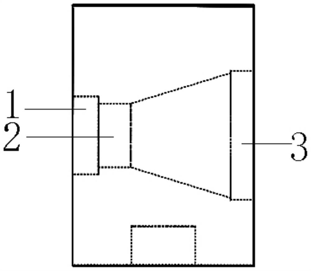
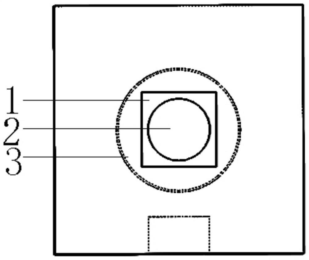
The invention discloses a high-efficiency solar blind ultraviolet light transmitting and receiving system. The transmitting end comprises a deep ultraviolet LED, a first optical lens and a second optical lens which are arranged in sequence; the receiving end comprises a third optical lens, a receiver internal light through hole, a light conversion material and a photoelectric detector which are arranged in sequence; a light source emitted by the deep ultraviolet LED sequentially passes through the three optical lenses and a light through hole in the receiver to the photoelectric detector; thetransmitting end compresses the light propagation angle through the two stages of lenses, good collimation is achieved, meanwhile, energy loss caused by the fact that light passes through the multiplestages of lenses is avoided, and the receiving end can select a direct detection scheme and a light conversion indirect detection scheme according to the difference of the used photoelectric detectors. The installation positions of all elements are simulated and optimized, the detection response is obviously improved after light conversion, and the photoelectric coupling efficiency is good. The system is simple in structure and low in cost, the detection sensitivity is effectively improved, and detection errors caused by accidental factors such as human factors and environment factors are reduced.

Description

technical field [0001] The invention belongs to the technical field of solar-blind ultraviolet light detection, in particular to a high-efficiency solar-blind ultraviolet light emitting and receiving system. Background technique [0002] Solar-blind ultraviolet light refers to light waves with a wavelength between 200-280 nm. Due to its unique atmospheric effect, the communication system using it as a carrier has the advantages of high confidentiality, anti-interference, and all-round and all-weather. The principle of solar-blind ultraviolet light communication is that the information electrical signal is modulated and loaded onto the sun-blind ultraviolet light carrier at the transmitting end, and a communication link is established by capturing and tracking the signal beam at the receiving end, and extracted through photoelectric conversion and demodulation processing. out the original information. [0003] Photodetectors are a class of devices that can convert optical si...

Claims


Application Information

Patent Timeline
Patent Type & Authority Patents(China)
IPC IPC(8): H04B10/11H04B10/50H04B10/67H04B10/69
CPCH04B10/11H04B10/501H04B10/502H04B10/67H04B10/69
Inventor 付丽丽许凯郑锐林韦玮
Owner NANJING UNIV OF POSTS & TELECOMM
Learn More