
High-temperature flue gas multi-stage backflow low-nitrogen combustor and combustion method thereof

A low-nitrogen burner and high-temperature flue gas technology, which is applied in the direction of combustion methods, gas fuel burners, burners, etc., can solve the problems of boiler stability, boiler thermal efficiency decline, and limited emission reduction effect, and achieve the elimination of incomplete combustion Stabilizing effect, reducing NOX generation, increasing the effect of stability

Pending Publication Date: 2020-04-17
TSINGHUA UNIV
View PDF0 Cites 4 Cited by
  • Summary
  • Abstract
  • Description
  • Claims
  • Application Information

AI Technical Summary

Problems solved by technology

Various low-nitrogen combustion technologies have both advantages and disadvantages. For example, air staged combustion is widely used, but the emission reduction effect is limited; flue gas recirculation is simple, but further reduces NO X Emissions will lead to unstable combustion and have a certain impact on the stability of the boiler; lean-burn premixed NOx emission reduction effect is good, but the thermal efficiency of the boiler will decrease, and may cause backfiring or flameout
The flue gas mixing technology in the furnace has been greatly developed in recent years. However, due to the use of the Venturi method for mixing, the uniformity of mixing and the amount of flue gas entrainment are affected by operating parameters, or it is impossible to reduce NO X generate or cause combustion instability

Method used


Image

  • High-temperature flue gas multi-stage backflow low-nitrogen combustor and combustion method thereof
  • High-temperature flue gas multi-stage backflow low-nitrogen combustor and combustion method thereof
  • High-temperature flue gas multi-stage backflow low-nitrogen combustor and combustion method thereof

Examples


Embodiment Construction

[0035] The specific embodiment of the present invention and working process will be further described below in conjunction with accompanying drawing.

[0036] The orientation terms such as up, down, left, right, front and rear in this application document are established based on the positional relationship shown in the drawings. If the drawings are different, the corresponding positional relationship may also change accordingly, so this should not be understood as limiting the scope of protection.

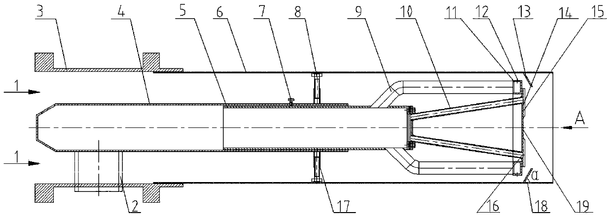
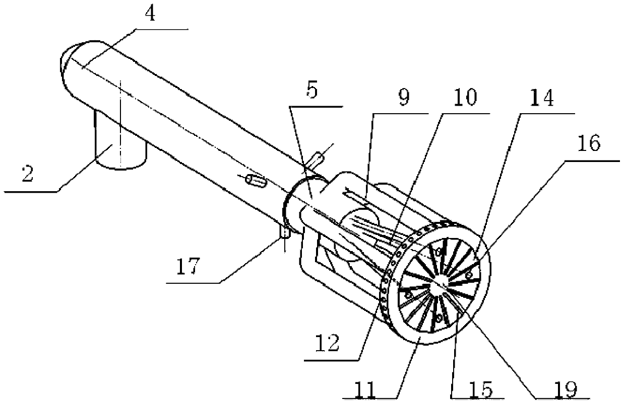
[0037] Such as figure 1 As shown, a high-temperature flue gas multi-stage return flow low-nitrogen burner includes a casing 3, a fuel main pipe 4 and a combustion head. The fuel main pipe 4 is concentrically arranged in the housing 3, and an air passage 1 is formed between the outer wall of the fuel main pipe 4 and the inner wall of the housing 3; the fuel injection end is in front, the inlet end is in the rear, and the combustion head is arranged on The front end of the main fu...


PUM


Abstract

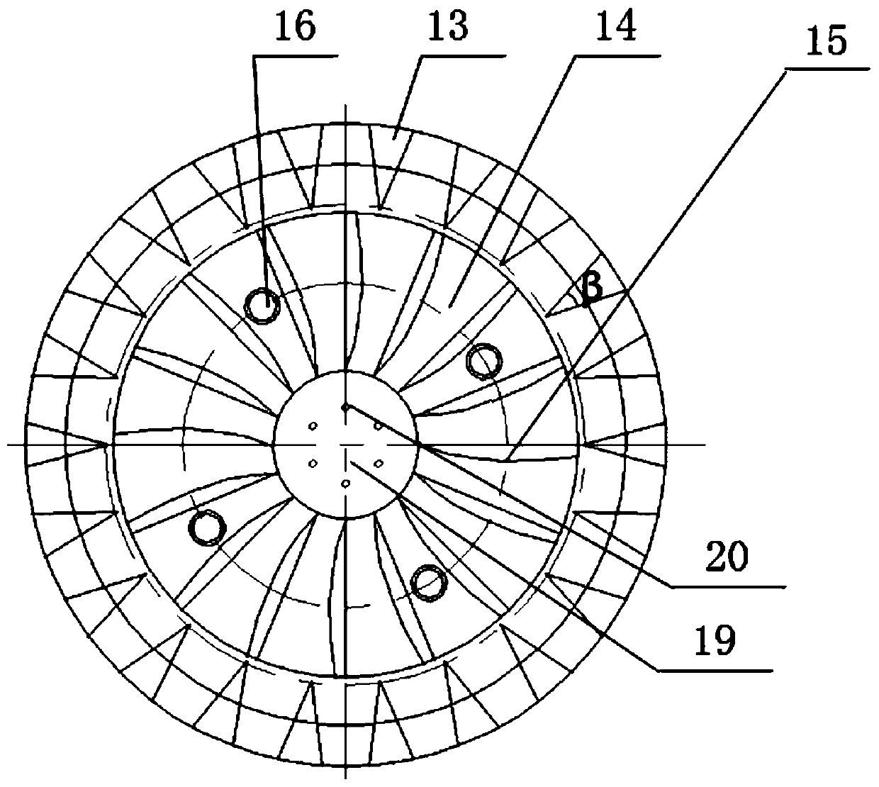
The invention discloses a high-temperature flue gas multi-stage backflow low-nitrogen combustor and a combustion method thereof. The combustor comprises a shell, a fuel main pipe and a combustion head, wherein the fuel main pipe is arranged in the shell, and an air channel is formed between the fuel main pipe and the shell; the combustion head comprises a connecting pipe, a secondary fuel pipe, aprimary fuel pipe, a secondary fuel distribution ring pipe and a rotational flow disc; the secondary fuel distribution ring pipe is arranged on the periphery of the rotational flow disc in a concentric circle mode, and the secondary fuel distribution ring pipe and the rotational flow disc jointly serve as an outlet of the combustion head; and vortex plates are arranged on the inner wall surface ofthe front end of the shell, and the vortex plates are arranged at flue gas backflow holes in a one-to-one correspondence mode. Primary air and fuel gas enter the combustor through the air channel andthe fuel main pipe correspondingly; and the fuel gas is divided into primary fuel gas and secondary fuel gas through the primary fuel pipe and the secondary fuel pipe correspondingly. The primary fuel gas forms an on-duty flame at the center of the rotational flow disc. The secondary fuel gas and air form high-speed jet flow, and high-temperature flue gas is entrained to form multi-stage backflow. The high-temperature flue gas multi-stage backflow low-nitrogen combustor has the advantages of fuel grading, flame dispersion, low NOx combustion and the like.

Description

technical field [0001] The invention relates to a high-temperature flue gas multi-stage backflow low-nitrogen burner and a combustion method thereof, belonging to the technical field of combustion. Background technique [0002] With the rapid development of the economy, the rapid increase of energy consumption and the severe situation of global warming, the problem of air pollution has attracted more and more attention. Nitrogen oxides (NOx) are one of the main pollutants in the atmosphere, which can not only form acid rain, but also form PM 2.5 key precursors. Therefore, further control of nitrogen oxide (NOx) emissions is crucial to sustainable development. For natural gas boilers, it is urgent to develop high-efficiency, low-nitrogen burners. [0003] At present, the main low-nitrogen combustion technologies include staged combustion, flameless combustion, flue gas recirculation, premixed combustion, etc. Its technical route mainly revolves around reducing the combust...

Claims


Application Information

Patent Timeline
Patent Type & Authority Applications(China)
IPC IPC(8): F23D14/04F23D14/26F23D14/46F23D14/70
CPCF23D14/04F23D14/26F23D14/46F23D14/70F23D2900/14021
Inventor 卓建坤刘畅张婧雯唐勇孙芳芳姚强
Owner TSINGHUA UNIV
Learn More