
Numerical control polishing device liquid supplied through inner flow channel

A polishing device and internal flow channel technology, applied in grinding/polishing equipment, parts of grinding machine tools, metal processing equipment, etc., can solve the problem of difficult to control the surface uniformity of polished workpieces, abrasive aggregation, and excessive wear of polishing pads, etc. problems, to achieve the effect of improving polishing efficiency and polishing surface quality, stable update speed, and uniform distribution of abrasive particles

Pending Publication Date: 2020-04-21
HUAQIAO UNIVERSITY
View PDF0 Cites 0 Cited by
  • Summary
  • Abstract
  • Description
  • Claims
  • Application Information

AI Technical Summary

Problems solved by technology

[0003] Although the traditional small grinding head polishing is widely used in the processing of hard and brittle materials, its disadvantage is that the polishing liquid is not evenly distributed under the grinding head under the action of centrifugal force and the abrasive renewal speed Slow, even local lack of polishing fluid or local abrasive accumulation during high-speed rotation, eventually leading to excessive wear of the polishing pad, reducing the service life of the polishing pad, increasing the cost of processing, and it is difficult to control the surface uniformity of the polished workpiece, which affects the hardness. Surface polishing effect of brittle materials

Method used


Image

  • Numerical control polishing device liquid supplied through inner flow channel
  • Numerical control polishing device liquid supplied through inner flow channel
  • Numerical control polishing device liquid supplied through inner flow channel

Examples


Embodiment

[0028] Embodiment: In order to verify the effect of the polishing tool of the present invention, the experimental device is installed according to the implementation steps, and the numerically controlled polishing device with the inner channel liquid supply provided by the present invention and the traditional peripheral liquid supply polishing device are respectively used in the same A comparative experiment of polishing high-alumina-silicon tempered glass was carried out under the process parameters. After the experiment, the wear of the polishing layer, that is, the polyurethane polishing pad under different liquid supply methods was observed under an ultra-depth-of-field microscope.

[0029] Figure 4 (a) is the surface morphology of the polyurethane polishing pad after internal liquid supply polishing for 30 minutes, Figure 4 (b) is the surface morphology of the polyurethane polishing pad after polishing with liquid supply around it for 30 minutes. from Figure 4 (a) ...


PUM


Abstract

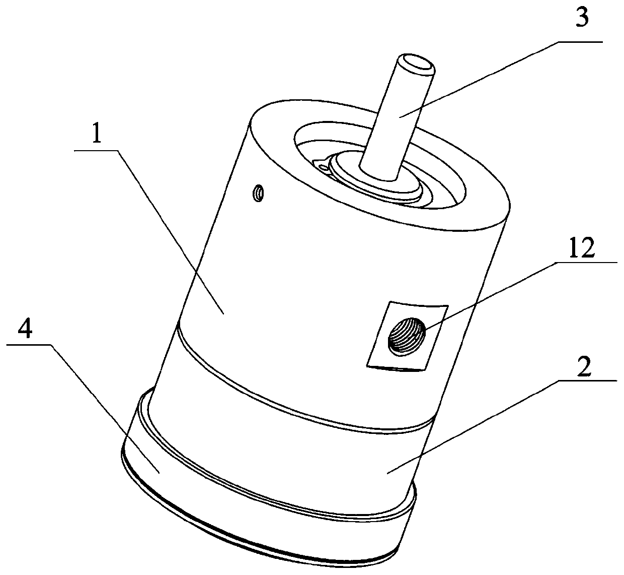
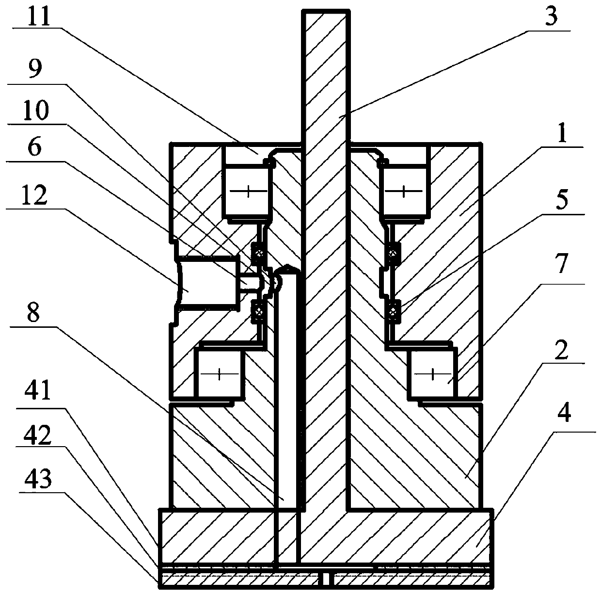
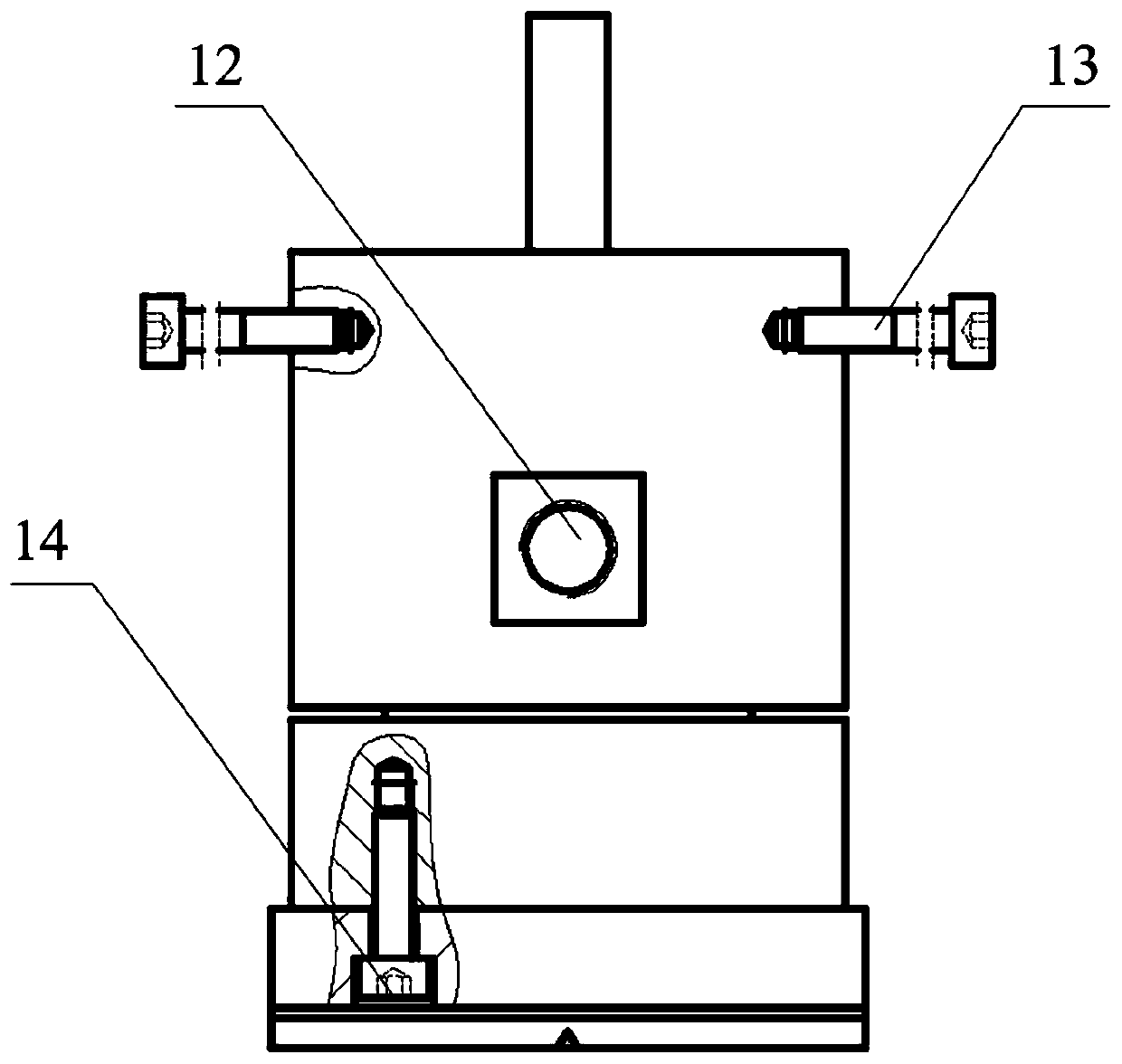
The invention provides a numerical control polishing device with liquid supplied through an inner flow channel. A stator shell is of a hollow structure, grooves for containing bearings are formed in the two ends of the stator shell, and the interior of the stator shell and a rotor shaft are dynamically sealed through an O-shaped sealing ring; a liquid inlet threaded hole is formed in the middle ofa side face of the stator shell, one end is connected with a polishing liquid supply pipe, the other end is communicated with a drainage groove, and two threaded holes are formed in an upper portionof a side face of the stator shell and are used for being connected with a stop rod. The rotor shaft is a T-shaped stepped hollow shaft, the rotor shaft is connected with the stator shell through a rolling bearing, a through hole for conveying polishing liquid is formed in the rotor shaft in the vertical direction, a plurality of blind holes are vertically connected to the periphery of the throughhole, the blind holes extend to an open hole in a side wall of the rotor shaft, and the blind holes are communicated with threaded holes in the side face of the stator shell sequentially through theopen hole and the drainage groove; a mandrel penetrates through the interior of the rotor shaft, an upper end is connected with a machine tool spindle through a spring chuck, and a lower end is connected with a polishing grinding head which is perpendicular to the mandrel, and the polishing grinding head and the mandrel are an integrated piece.

Description

technical field [0001] The invention relates to the technical field of processing tools for hard and brittle materials, in particular to a numerically controlled polishing device for liquid supply through an inner channel. Background technique [0002] The traditional small grinding head polishing adopts the processing method of free abrasive and solid grinding head. The driving shaft is perpendicular to the solid grinding head and is rigidly connected. There is a polishing pad at the bottom of the solid grinding head. The workpiece is in contact with each other, and the rotation of the polishing pad drives the free abrasive to perform sliding, plowing, and micro-cutting on the surface of the workpiece to achieve material removal. [0003] Although the traditional small grinding head polishing is widely used in the processing of hard and brittle materials, its disadvantage is that the polishing liquid is not evenly distributed under the grinding head under the action of cent...

Claims


Application Information

Patent Timeline
IPC IPC(8): B24B41/04B24B57/02
CPCB24B41/04B24B57/02
Inventor 沈剑云陶萍钱锋
Owner HUAQIAO UNIVERSITY
Learn More