Micro-fluidic chip used for particle control

A microfluidic chip and particle technology, applied to laboratory containers, laboratory utensils, chemical instruments and methods, etc., can solve the problem of difficult to achieve small-sized particle clamping, difficult to achieve single particle clamping, lack of reliable Solutions and other issues, to achieve the effect of slowing down the flow rate, improving the sensitivity, and maintaining the air bubbles

Pending Publication Date: 2020-04-24
SUZHOU INST OF BIOMEDICAL ENG & TECH CHINESE ACADEMY OF SCI
View PDF4 Cites 8 Cited by
  • Summary
  • Abstract
  • Description
  • Claims
  • Application Information

AI Technical Summary

Problems solved by technology

[0003] 1. It is difficult to clamp a single particle in this way. The particles are distributed in the entire flow channel and often gather together under the action of the sound field;
[0004] 2. When the size of the flow channel is large, if the standing wave wavelength is adapted to the size of the flow channel in order to ensure a single node, and the frequency is low and the acoustic radiation force is small, it is difficult to clamp small-sized particles
[0005] 3. When

Method used


Image

  • Micro-fluidic chip used for particle control
  • Micro-fluidic chip used for particle control
  • Micro-fluidic chip used for particle control

Examples


Embodiment 1

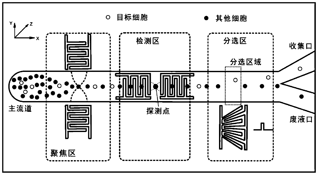
[0059] refer to figure 1 A pair of focusing interdigital electrodes 31 are set in the focusing area 3 for three-dimensional focusing of the particles, a pair of clamping interdigital electrodes 40 arranged along the particle flow direction are arranged in the detection area 4, and a pair of clamping interdigital electrodes 40 arranged along the particle flow direction is arranged in the focusing area 5, and a The interdigitated electrodes 50 are sorted.

Embodiment 2

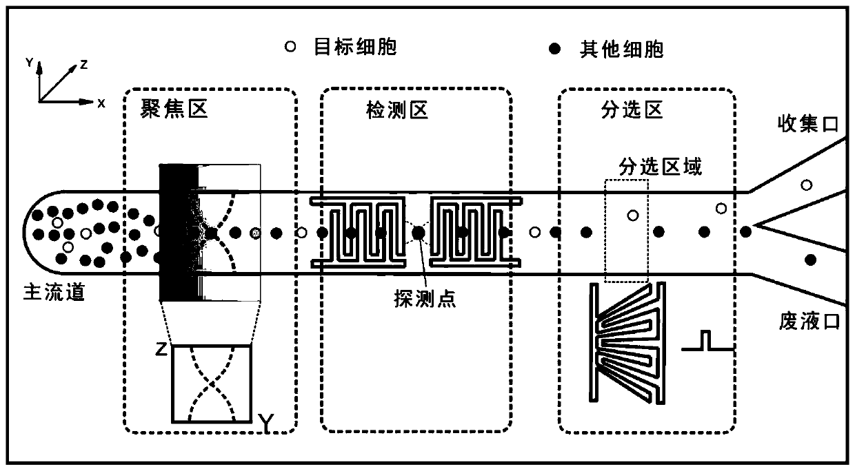
[0061] refer to figure 2 , a piezoelectric transducer 30 is set in the focusing area 3 for three-dimensional focusing of the particles, a pair of clamping interdigital electrodes 40 arranged along the particle flow direction are set in the detection area 4, a The interdigitated electrodes 50 are sorted.

Embodiment 3

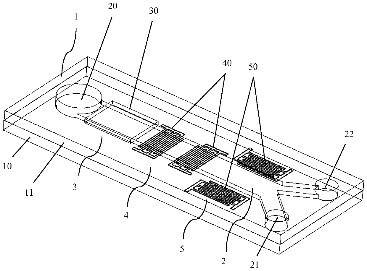
[0063] refer to image 3 , 4 , a piezoelectric transducer 30 is set in the focusing area 3 for three-dimensional focusing of the particles, a pair of clamping interdigital electrodes 40 arranged along the flow direction of the particles is set in the detection area 4, and a pair of clamping interdigital electrodes 40 arranged in the flow direction of the particles is set in the detection area 5, and a pair of interdigital electrodes 40 perpendicular to the flow direction of the particles is set in the separation area 5. The interdigitated electrodes 50 are sorted.


PUM


Abstract

The invention relates to a micro-fluidic chip which comprises a chip body and a flow channel structure arranged in the chip body, and a main flow channel of the flow channel structure is sequentiallyprovided with a focusing area, a detection area and a sorting area in the particle flowing direction, wherein the focusing area is used for realizing focusing of particles in the main flow channel ina three-dimensional space, the detection area is used for clamping and detecting target particles, and the sorting area is used for realizing sorting of the target particles and non-target particles.According to the invention, single particles in the continuous flow micro-channel can be fixed at a certain position, time is provided for detection, and the detection of the particles is facilitated;acoustic waves are adopted to push particles in fluid to move, and mechanical force acts on the particles, so that the activity of the particles is not affected; the particles are controlled by adopting sound waves, the sample flux is high, the flow velocity is reduced, and the improvement of the subsequent detection sensitivity is facilitated; the flow channel is simple in structure, the numberof the flow ports is small, and bubble discharging and fluid environment stability maintaining are facilitated.

Description

technical field [0001] The invention relates to the field of microfluidic chip, biological particle detection and manipulation technology, and in particular to a microfluidic chip for particle manipulation. Background technique [0002] Microfluidics integrates the basic operation units such as sample preparation, reaction, separation, and detection in the biological, chemical, and medical analysis processes into a micron-scale chip to automatically complete the entire analysis process. Due to its great potential in the fields of biology, chemistry, and medicine, it has developed into a new research field interdisciplinary in biology, chemistry, medicine, fluid, electronics, materials, and machinery. Microfluidic chips are widely used to realize the detection and manipulation of particles. Acoustic tweezers technology based on the principle that particles move to nodes in the standing wave sound field has the function of fixing the position of the particles, so as to facili...

Claims


Application Information

Patent Timeline
IPC IPC(8): B01L3/00
CPCB01L3/502761B01L2200/12B01L2300/0816
Inventor 马玉婷王策宋飞飞裴智果严心涛吴云良钟金凤陈忠祥
Owner SUZHOU INST OF BIOMEDICAL ENG & TECH CHINESE ACADEMY OF SCI
Why Eureka
Try Eureka