Method for accurately machining deep hole

A kind of machining and deep hole technology, applied in the field of mechanical processing of metal materials, can solve the problems of increasing processing procedures, poor lubrication, uneven force, etc., and achieve the effect of ensuring the success rate

Inactive Publication Date: 2020-04-28
西安稀有金属材料研究院有限公司
View PDF6 Cites 1 Cited by
  • Summary
  • Abstract
  • Description
  • Claims
  • Application Information

AI Technical Summary

Problems solved by technology

[0003] The processing method of deep hole is generally drilling, that is, the cutting process is completed by using the rotating tool holder to fix the workpiece. One of the most difficult problems faced by deep hole processing is that it is difficult to ensure the verticality of the deep hole. For deep hole processing, the tool holder In the process of moving forward, problems such as uneven force, poor lubrication, and untimely cooling may be encountered, resulting in errors in the perpendicularity between the tool holder and the processing plane. During deep hole processing, small errors continue to accumulate , which eventually leads to a large deviation in the verticality of the deep hole, and such deviation is difficult to predict or control, resulting in a sharp increase in the difficulty of precisely machining the deep hole, which brings risks to the processing of related parts and equipment; Due to the limitation of the hole diameter, during the cutting process, with the increase of the stroke of the tool rod, it is very easy to produce the tool vibration phenomenon, resulting in an increase in the roughness of the hole wall, which is difficult to meet the processing requirements; at the same time, when cutting between the tool and the metal, It is difficult for coolant and lubricant to enter the cutting area, resulting in local overheating, which reduces the wear resistance and life of the tool; in the process of deep hole machining, the cutting condition of the tool cannot be directly observed, but can only be heard by listening to the cutting sound, watching Indirect methods such as the appearance of chips and the vibration amplitude of the cutter bar can be used to judge whether the cutting process is smooth or not, which increases the difficulty and threshold of deep hole processing
[0004] Faced with this situation, there are currently relevant technical improvement measures, which can be roughly divided into the following two categories: The first category is to upgrade processing equipment, such as improving the rigidity of the drill bit and the accuracy of the machine tool. There is still no possibility of fundamentally avoiding the deviation of the verticality of the deep hole, and it also increases the processing cost; the second type is to increase the processing process, such as drilling the pilot hole first, and then using the drill to ream the hole to process the specified hole diameter. Although this method can ensure the roughness of the inner wall of the deep hole, the guide hole is still processed by traditional technology, and its verticality is difficult to guarantee. Therefore, this method is still difficult to guarantee the shape and position tolerance of the deep hole

Method used


Image

  • Method for accurately machining deep hole
  • Method for accurately machining deep hole
  • Method for accurately machining deep hole

Examples


Embodiment 1

[0040] Present embodiment is the deep hole of 30mm * 717mm (aperture * hole depth) of 0.05mm processing parallelism on the TC4 titanium alloy cylindrical ingot of 400mm * 717mm (diameter * height), wherein, TC4 titanium alloy cylindrical ingot such as Figure 7 as shown, Figure 7 The middle TC4 titanium alloy cylindrical ingot has a blind hole 9 with a diameter of a=145mm and a hole depth of b=637mm, the distance from the bottom surface of the blind hole 9 on the TC4 titanium alloy cylindrical ingot to the bottom surface of the TC4 titanium alloy cylindrical ingot c = 80mm, and the diameter of the TC4 titanium alloy cylindrical ingot is d = 400mm.

[0041] This embodiment includes the following steps:

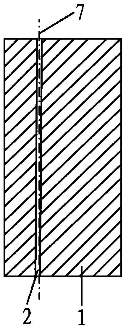
[0042] Step 1, the TC4 titanium alloy cylindrical ingot is drilled centered on the axis 7 of the designed deep hole on the TC4 titanium alloy cylindrical ingot to obtain a TC4 titanium alloy cylindrical ingot with a threading hole 2, such as Figure 8 Shown; The aperture of ...

Embodiment 2

[0068] This implementation is to process a deep hole of 24mm × 680mm (aperture × hole depth) with a parallelism of 0.1mm on a 304L stainless steel cube part with a side length of 680mm.

[0069] This embodiment includes the following steps:

[0070] Step 1, the 304L stainless steel cube part is centered on the axis 7 of the design deep hole on the 304L stainless steel cube part to carry out the drilling process to obtain the 304L stainless steel cube part with the threading hole 2; the aperture of the threading hole 2 is 6mm ;

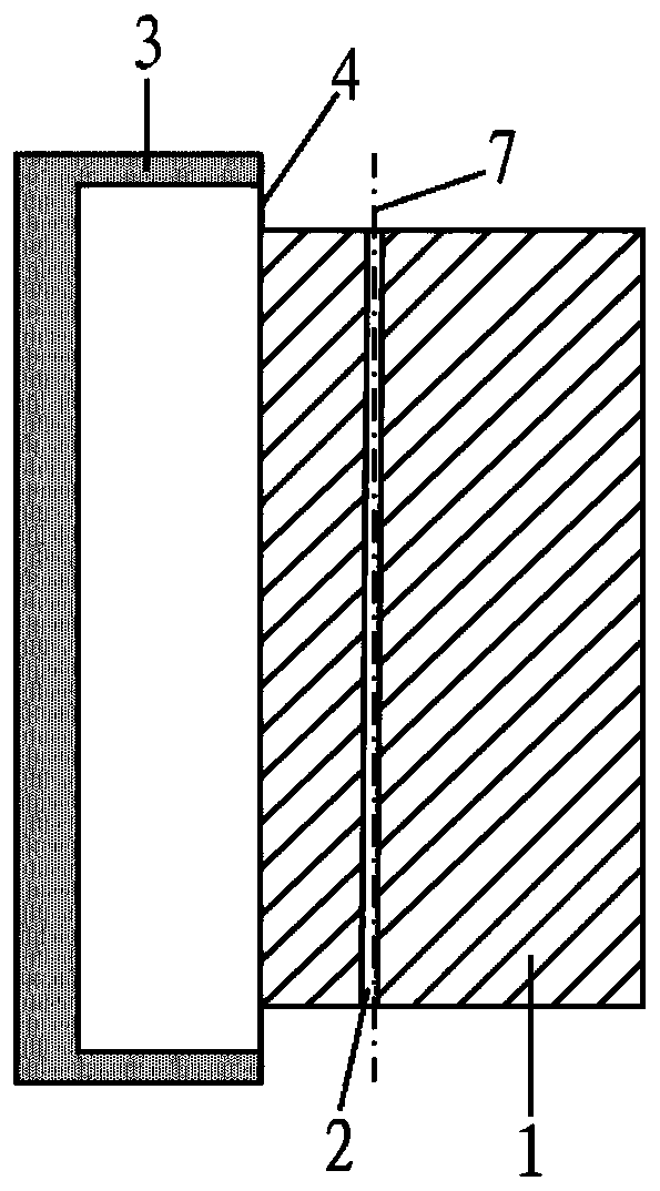
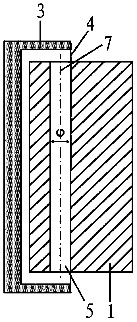
[0071] Step 2, first place the 304L stainless steel cube part with the threading hole 2 obtained in step 1 on the fixture of the wire electric discharge machine 3, and adjust the part with the threading hole 2 by adjusting the fixture of the wire electric discharge machine 3 The position of the 304L stainless steel cube part is until the three reference points are found on the axis 7 of the designed deep hole on the 304L stainless steel cube part with t...

Embodiment 3

[0077] This implementation is to process a deep hole of 35mm * 800mm (diameter * hole depth) with a parallelism of 0.1mm on a 6061 aluminum alloy cylindrical ingot of 500mm * 800mm (diameter * height).

[0078] This embodiment includes the following steps:

[0079] Step 1. Drilling the 6061 aluminum alloy cylindrical ingot centered on the axis 7 of the designed deep hole on the 6061 aluminum alloy cylindrical ingot to obtain a 6061 aluminum alloy cylindrical ingot with a threading hole 2; the threading The diameter of hole 2 is 7mm;

[0080] Step 2, first place the 6061 aluminum alloy cylindrical ingot with the threading hole 2 obtained in step 1 on the fixture of the wire electric discharge machine 3, and adjust the threading hole by adjusting the fixture of the wire electric discharge machine 3 2 The position of the 6061 aluminum alloy cylindrical ingot, until the three reference points are found on the axis 7 of the designed deep hole on the 6061 aluminum alloy cylindrical...


PUM


Abstract

The invention discloses a method for accurately machining a deep hole. The method comprises the following steps of 1, drilling a metal material by taking the axis of a designed deep hole as the centerto obtain the metal material with a threading hole; 2, carrying out wire cutting treatment on the metal material with the threading hole by taking the axis of the designed deep hole as the center, and obtaining the metal material with a guide hole; and 3, carrying out deep-hole accurate machining on the metal material with the guide hole along the guide hole through a drill bit, and obtaining themetal material with the precisely machined deep hole. According to the method, the threading hole is machined in the metal, it is guaranteed that a wire electrode for electric spark wire cutting cansmoothly penetrate through the threading hole, the guide hole with the perpendicularity meeting the requirement is machined through wire cutting, the advancing path of the drill bit is kept parallel to the guide hole, the deep hole is machined by the drill bit, and deep-hole accurate machining is achieved, the method is controllable in precision and extremely high in success rate, and the roughness and the form and location tolerance of the machined deep hole completely meet the design requirements.

Description

technical field [0001] The invention belongs to the field of mechanical processing of metal materials, and in particular relates to a method for precisely machining deep holes. Background technique [0002] Deep holes generally refer to holes whose depth-to-aperture ratio is greater than 5. Under certain circumstances, the ratio of hole depth to aperture can even be greater than 100. Deep holes can be used for assembly, positioning, and guidance in parts or products. It is widely used in bearings, valves, rocket bodies, artillery barrels and other special equipment. [0003] The processing method of deep hole is generally drilling, that is, the cutting process is completed by using the rotating tool holder to fix the workpiece. One of the most difficult problems faced by deep hole processing is that it is difficult to ensure the verticality of the deep hole. For deep hole processing, the tool holder In the process of moving forward, problems such as uneven force, poor lubri...

Claims


Application Information

Patent Timeline
IPC IPC(8): B23P15/00B23H9/14
CPCB23H9/14B23P15/00
Inventor 刘承泽吴金平赵彬卢振远张于胜
Owner 西安稀有金属材料研究院有限公司
Why Eureka
Try Eureka