
Suspension type floating bridge

A kind of racking and overpass technology, applied in the direction of coating, transportation and packaging, anti-corrosion coatings, etc., can solve the problems of increasing tires, mechanical wear and fuel consumption, consuming energy and resources, increasing operating costs, etc., to achieve shock absorption and buffering Good effect, reduce bearing capacity and improve cushioning performance

Inactive Publication Date: 2020-04-28
十堰创胜工贸有限公司
View PDF0 Cites 0 Cited by
  • Summary
  • Abstract
  • Description
  • Claims
  • Application Information

AI Technical Summary

Problems solved by technology

Multi-axle bridges can increase the bearing capacity, but they will increase unnecessary tires, mechanical wear and fuel consumption when returning empty vehicles, which virtually increases operating costs and consumes energy and resources
[0003] The current floating bridge has poor shock absorption performance, poor bearing capacity, and is easy to be deformed and damaged. Therefore, it is necessary to improve

Method used


Image

  • Suspension type floating bridge
  • Suspension type floating bridge
  • Suspension type floating bridge

Examples


Embodiment 1

[0024] The upper and lower bridges are sprayed with a wear-resistant material layer. The components of the wear-resistant material layer include 20 parts by weight of aluminum oxide, 4 parts of titanium oxide, 5 parts of zirconia, 5 parts of silicon calcium barium, and 8 parts of quartz sand. 4 parts of titanium carbide, 3 parts of fly ash floating beads, 2 parts of graphite powder, 2 parts of carbon fiber, 4 parts of sintered mullite, and 2 parts of wood fiber.

Embodiment 2

[0026] The upper and lower bridges are sprayed with a wear-resistant material layer. The components of the wear-resistant material layer include 30 parts by weight of aluminum oxide, 10 parts of titanium oxide, 15 parts of zirconia, 12 parts of silicon calcium barium, and 20 parts of quartz sand. 10 parts of titanium carbide, 9 parts of fly ash floating beads, 8 parts of graphite powder, 6 parts of carbon fiber, 12 parts of sintered mullite, and 5 parts of wood fiber.

Embodiment 3

[0028] The upper and lower bridges are sprayed with a wear-resistant material layer. The components of the wear-resistant material layer include 25 parts by weight of aluminum oxide, 7 parts of titanium oxide, 10 parts of zirconia, 8 parts of silicon-calcium-barium, and 14 parts of quartz sand. 7 parts of titanium carbide, 6 parts of fly ash floating beads, 5 parts of graphite micropowder, 4 parts of carbon fiber, 8 parts of sintered mullite, and 4 parts of wood fiber.

[0029] In the present invention, the wear-resistant material layer sprayed on the exterior of the upper bridge and the lower bridge has good wear resistance and corrosion resistance, and prevents the bridge from rusting. In the present invention, the wear-resistant material layer sprayed on the exterior of the upper bridge and the lower bridge has good wear resistance and corrosion resistance, and prevents the bridge from rusting.


PUM


Abstract

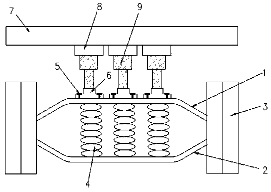
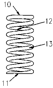
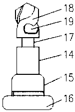
The invention discloses a suspension type floating bridge. The suspension type floating bridge comprises an upper overpass and a lower overpass, and the upper overpass and the lower overpass are arranged in parallel up and down; tires are respectively mounted at two ends of the upper overpass and the lower overpass; a plurality of groups of damping springs are arranged between the upper overpass and the lower overpass; mounting blocks are fixedly mounted on the upper end surface of the upper overpass through bolts; and a cross beam at the bottom portion of a vehicle is arranged above the upperoverpass, a plurality of oil cylinder mounting seats corresponding to the mounting blocks are arranged at the inner side of the cross beam, and flexible oil cylinders are installed between the oil cylinder mounting seats and the mounting blocks. The suspension type floating bridge has the advantages that the suspension type floating bridge is novel in structural design and good in damping and buffering effect, the purpose of automatic lifting can be achieved, and the bearing capacity of the floating bridge can be effectively reduced.

Description

technical field [0001] The invention relates to the technical field of floating bridges, in particular to a suspension type floating bridge. Background technique [0002] With the continuous improvement of road grades in our country, trucks are also developing towards high speed and heavy load. The supporting heavy-duty axles have also made great progress in recent years. The output of FAW 457 axles, Dongfeng wheelside axles, 460 axles, Sinotruk's Steyr axles and North Mercedes-Benz wheelside axles has been increasing year by year, and they are favored by users. . The vehicle layout of heavy-duty vehicles has also developed from the initial two-axle (front and rear axles) to today's three-axle (front, middle and rear axles) and four-axle (double front axles, middle and rear axles). Multi-axle bridges can increase the bearing capacity, but they will increase unnecessary tires, mechanical wear and fuel consumption when returning empty vehicles, which virtually increases oper...

Claims


Application Information

Patent Timeline
Patent Type & Authority Applications(China)
IPC IPC(8): B60B35/00C09D1/00C09D5/08C09D7/61C09D7/65
CPCB60B35/007C09D1/00C09D5/08C09D7/61C09D7/65C09D7/70
Inventor 罗荣海
Owner 十堰创胜工贸有限公司
Learn More