Microstrip antenna, anti-metal electronic tag and manufacturing method of anti-metal electronic tag

A technology of microstrip antenna and antenna, which is applied in the direction of recording carriers, instruments, computer parts and other parts used by machines, can solve the problems of data reading and writing, achieve the effect of reducing size, easy implementation, and improving the reading distance

Active Publication Date: 2020-04-28
上海炘璞电子科技有限公司
View PDF11 Cites 4 Cited by
  • Summary
  • Abstract
  • Description
  • Claims
  • Application Information

AI Technical Summary

Problems solved by technology

[0010] In view of the above problems in the prior art, the present invention provides a microstrip antenna and an electronic tag, wh

Method used


Image

  • Microstrip antenna, anti-metal electronic tag and manufacturing method of anti-metal electronic tag
  • Microstrip antenna, anti-metal electronic tag and manufacturing method of anti-metal electronic tag
  • Microstrip antenna, anti-metal electronic tag and manufacturing method of anti-metal electronic tag

Examples


Embodiment Construction

[0069] In order to further explain the technical means and effects that the present invention takes to achieve the intended purpose of the invention, the specific implementation of the microstrip antenna, electronic tag and electronic tag manufacturing method according to the present invention will be described below in conjunction with the accompanying drawings and preferred embodiments , structure, feature and effect thereof, detailed description is as follows.

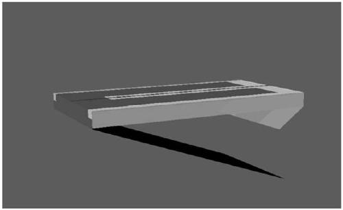
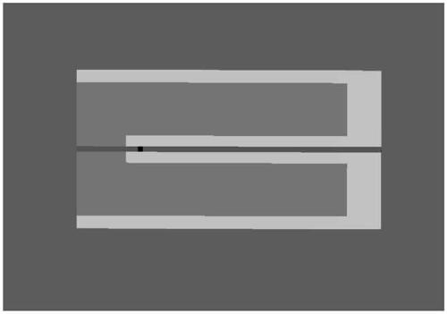
[0070] Such as Figure 2-5 As shown, in the first preferred embodiment of the present invention, the microstrip antenna of the present invention includes a ground plate 20, a radiation sheet including a sub-chip 211 and a sub-chip 212, a medium 26, a feed source 22, a feeder 23, a short circuit sheet 27, feeder sheet 24 and insulating film. Wherein, the medium 26 is substantially a flat cuboid structure, and in this embodiment it is formed of an elastic material, such as silicon rubber. exist image 3 In the XYZ ...


PUM

PropertyMeasurementUnit
Thicknessaaaaaaaaaa
Widthaaaaaaaaaa

Abstract

A microstrip antenna includes: a radiation sheet; a grounding plate parallel to the radiation sheet; a short-circuit sheet conductively connected with the radiation sheet and the grounding plate; and a feed sheet positioned between the radiation sheet and the grounding plate; wherein the radiation sheet is provided with a slit so that the radiation sheet is U-shaped as a whole, and the U-shapedradiation sheet comprises two sub-sheets forming two arms of the U-shaped radiation sheet and a connecting part forming the bottom edge of the U-shaped radiation sheet; a feed source is arranged in the slit, one of a positive electrode and a negative electrode of the feed source is electrically connected with the connecting part, and the other one of the positive electrode and the negative electrode of the feed source is electrically connected with the feed sheet through a feed line; wherein the bottom side of the feed sheet is arranged to cling to the grounding plate and is separated from thegrounding plate through an insulating film, and the thickness of the insulating film is far less than 1/4 wavelength corresponding to the resonant frequency of the microstrip antenna. The microstripantenna provided by the invention is easy to realize mass production and keep consistent performance, has good metal resistance, is easy to adjust, and can be adapted to different frequency band requirements of different countries and regions in a simple manner.

Description

technical field [0001] The invention relates to the technical field of wireless communication, in particular to a microstrip antenna, an electronic tag with anti-metal function and a manufacturing method of the electronic tag. Background technique [0002] Nowadays, more and more commodities are included in the Internet of Things system, and the use of electronic tags is becoming more and more extensive. At present, the cheapest electronic tags are ultra-high frequency electronic tags that work at UHF (Ultra High Frequency) frequency. The UHF RFID frequency band applicable to Europe is the ETSI frequency band (865-868MHz), and the UHF RFID frequency band applicable to the United States. The RFID frequency band is the FCC frequency band (902-928MHz), and its main frequency in China is 915MHz. Different from the previous two generations of 125KHz and 13.56MHz magnetic induction coupling data transmission, UHF RFID adopts the direct transmission of electromagnetic waves simila...

Claims


Application Information

Patent Timeline
IPC IPC(8): G06K19/073G06K19/077
CPCG06K19/07318G06K19/07773
Inventor 蔡发军徐立宇宗欣
Owner 上海炘璞电子科技有限公司
Why Eureka
Try Eureka