Cell micro-scalpel based on optical fiber optical hand, and manufacture method for cell micro-scalpel

A micro-scalpel and low-light technology, applied in the field of single-cell manipulation, can solve the problems of low flexibility and large volume of the spatial light system, and achieve the effect of precise cell surgical positioning

Active Publication Date: 2020-05-08
GUILIN UNIV OF ELECTRONIC TECH
View PDF11 Cites 2 Cited by
  • Summary
  • Abstract
  • Description
  • Claims
  • Application Information

AI Technical Summary

Problems solved by technology

However, spatial light systems generally have the disadvantages of large volume and low flexibility.

Method used


Image

  • Cell micro-scalpel based on optical fiber optical hand, and manufacture method for cell micro-scalpel
  • Cell micro-scalpel based on optical fiber optical hand, and manufacture method for cell micro-scalpel
  • Cell micro-scalpel based on optical fiber optical hand, and manufacture method for cell micro-scalpel

Examples


Embodiment 1

[0049] Example 1: The fiber-optic low-light hand has a powerful cell posture adjustment function.

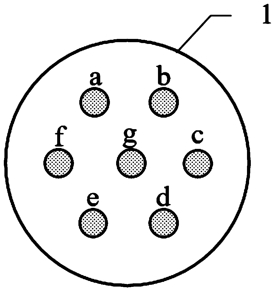
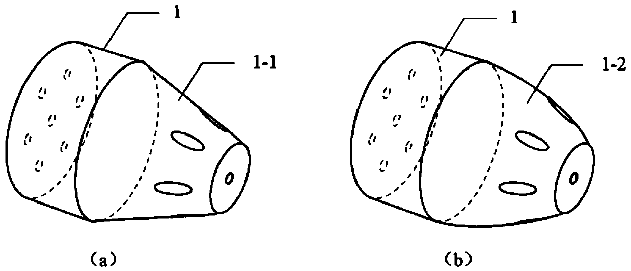
[0050] This embodiment adopts seven-core optical fiber to describe the present invention in detail, as figure 1 What is shown is a schematic view of the end face of the seven-core optical fiber 1 . The optical fiber has a central core and six peripheral cores distributed coaxially and annularly. In order to reflect and converge the captured light transmitted in the surrounding fiber core to form a trapping potential well, it is necessary to prepare a reflective frustum conical structure at the fiber end by precision grinding, such as figure 2 As shown, the frustoconical structure can be as figure 2 (a) shows the frustum of conical structure 1-1. Of course, in order to make the beam focus better and make the cell capture effect more stable, you can figure 2 The frustum structure in (a) is optimized to form an arc-shaped reflective frustum structure 1-2, such as figure 2 ...

Embodiment 2

[0053] Example 2: Cell high-precision, minimally invasive surgery function.

[0054] Such as Figure 5 As shown in (a), the single cell 9 is stably captured by the low-light hand of the seven-core optical fiber and its posture is adjusted so that the site to be operated on of the cell 9 faces the end face of the optical fiber. Figure 5 (b) is a cross-sectional view along the fiber axis. In addition to the truncated conical structure 1-1 that reflects and captures the beam, the fiber end of the seven-core fiber is also etched with a 10um×10um×10um concave in the middle of the fiber end face. Groove 13, groove 13 has microsphere lens 12 adhered with low refractive index glue. Figure 5 (c) is an enlarged view of the groove 13. The light beam output by the middle core of the seven-core optical fiber 1 is compressed by the microsphere lens 12, and can form a needle-shaped photon jet 14 in the axial direction outside the end face of the optical fiber, that is, this patent The Mi...

Embodiment 3

[0066] Example 3: The preparation method of cell micro-surgical knife based on optical fiber micro-light hand.

[0067] Step 1: Take a multi-core optical fiber 1, cut it flat, and use a femtosecond laser to etch a groove 13 on its end face, with a size of 10um×10um×10um;

[0068] Step 2: place a microsphere lens in the groove, and use low refractive index glue to cure the microsphere lens 12 in the center of the groove 13;

[0069] Step 3: Precisely grind and polish the end face, remove the excess adhesive layer 15, and make the end face of the multi-core optical fiber smooth;

[0070] Step 4: Precisely grind the end of the optical fiber to prepare a symmetrical reflective frusto-conical structure 1-1, polish it, clean it ultrasonically, and dry it with nitrogen gas before use.


PUM

PropertyMeasurementUnit
refractive indexaaaaaaaaaa

Abstract

The invention provides a cell micro-scalpel based on an optical fiber optical hand, and a manufacture method for the cell micro-scalpel. The cell micro-scalpel is composed of a multi-core optical fiber optical hand and a micro globe lens embedded into the end surface of an optical fiber, wherein the multi-core optical fiber optical hand can stably capture a target cell and can rotatably regulate the gesture of the captured cell; the center position of the end surface of the multi-core optical fiber is etched with a microgroove; the micro globe lens adheres into the microgroove; a light beam ofa middle fiber core is compressed through the micro globe lens to be output; and a light knife with high local energy density is formed and acts on the captured cell. The cell micro-scalpel can be used for the capture manipulation and the stereotaxic surgery, including operations of single cell perforation, single organelle removal, multi-cell fusion and the like, of a single cell. The cell micro-scalpel can be widely used for the bioscience research field of a single cell level.

Description

[0001] (1) Technical field [0002] The present invention relates to a cell micro-surgical knife based on optical fiber low-light hands and its preparation method, which can be used for single-cell capture manipulation, positioning surgery, including perforation of single cells, removal of single organelles, fusion of multiple cells, etc. , belonging to the technical field of single cell manipulation. [0003] (2) Background technology [0004] The development of modern life science largely depends on the processing and manipulation of living cells, such as the removal of some specific proteins or organelles in cells. Laser cell microsurgery is a powerful tool. In recent years, great progress has been made in the precision control of cell microsurgery, and a new discipline of laser cell biology has emerged. The cell itself is small in size, with a diameter of only a few microns to more than ten microns, and the internal structure of the cell is more delicate and complex. There...

Claims


Application Information

Patent Timeline
Patent Type & Authority Applications(China)
IPC IPC(8): C12M1/00
CPCC12M35/02
Inventor 苑立波杨世泰
Owner GUILIN UNIV OF ELECTRONIC TECH
Why Eureka
Try Eureka