Ultra-low-speed high-precision positioning control method of frameless torque motor

A torque motor and positioning control technology, which is applied in motor generator control, AC motor control, electronic commutation motor control, etc., can solve the problems of unable to suppress torque ripple, large flux compensation error, and large computational complexity. Achieve the effect of large self-disturbance rejection moment, small calculation amount and high positioning accuracy

Active Publication Date: 2020-05-08
CHONGQING UNIV
View PDF8 Cites 2 Cited by
  • Summary
  • Abstract
  • Description
  • Claims
  • Application Information

AI Technical Summary

Problems solved by technology

[0003] Problems with the above algorithms: Algorithm 1 has small self-disturbance rejection torque when running at ultra-low speed (below 0.2RPM), and there will be obvious torque ripple; Torque ripple at low speed; Algorithm 3 selects only one output voltage vector each time, which will cause a large error in flux linkage compensation, resulting in a large torque ripple; Algorithm 4 has switching chatter, which will also lead to Algorithm 5 increases the upper limit of motor speed, which is not helpful for smooth operation at ultra-low speeds; Algorithms 6, 7, and 8 are all intelligent optimization algorithms: Algorithm 6 requires a large number of training sets, has high computational complexity, and is limited in application scenarios ; Algorithms 7 and 8 require precise mathematical models, and poor adaptability under different working conditions

Method used


Image

  • Ultra-low-speed high-precision positioning control method of frameless torque motor
  • Ultra-low-speed high-precision positioning control method of frameless torque motor
  • Ultra-low-speed high-precision positioning control method of frameless torque motor

Examples


Embodiment 1

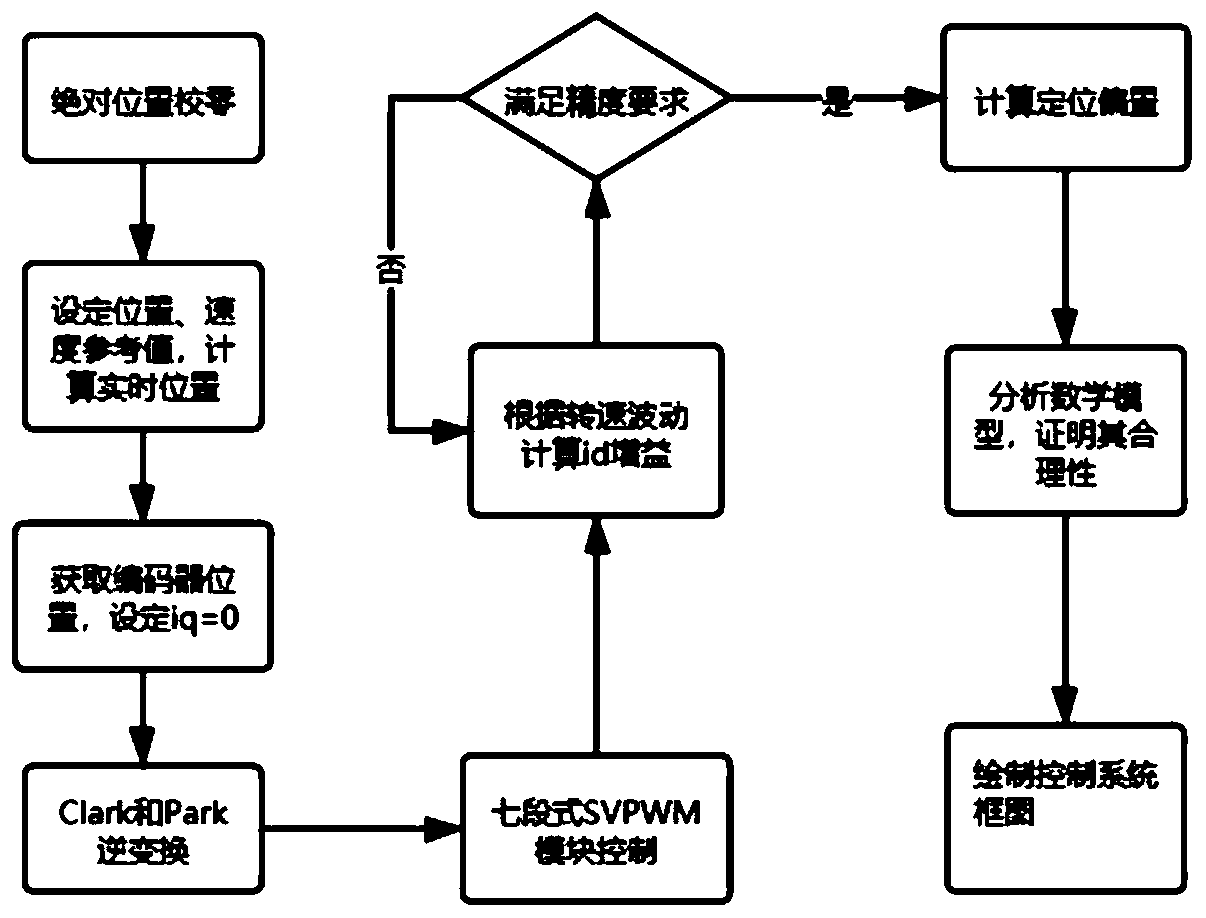
[0057] see Figure 1 to Figure 9 , an ultra-low-speed high-precision positioning control method for a frameless torque motor, mainly comprising the following steps:

[0058] 1) Connect the encoder coaxially with the motor rotor, and adjust the absolute position of the motor to zero.

[0059] The absolute position of the motor is zero calibration time t 0 The encoder angle read when the inner motor rotates to a position where the electrical angle is 0°.

[0060] 2) Set the reference value θ of the target position of the motor rotation tar and the reference value of rotation speed x tar , and calculate the mechanical angle θ the motor should rotate m , the electrical angle θ that should be rotated e , Motor real-time position θ real and motor real-time speed ω r .

[0061] The mechanical angle θ that the motor should rotate at the current moment t m and electrical angle θ e As follows:

[0062]

[0063] In the formula, n is the number of pole pairs of the motor.

...

Embodiment 2

[0109] An ultra-low-speed and high-precision positioning control method for a frameless torque motor, mainly comprising the following steps:

[0110] 1) Connect the encoder coaxially with the motor rotor, and adjust the absolute position of the motor to zero.

[0111] 2) Set the reference value θ of the target position of the motor rotation tar and the reference value of rotation speed x tar , and calculate the mechanical angle θ the motor should rotate m , the electrical angle θ that should be rotated e , Motor real-time position θ real and motor real-time speed ω r .

[0112] 3) Given the excitation current i of the motor d , and maintain the torque current i q =0. Through the coordinate inverse conversion and the seven-segment voltage space vector PWM control module, the switch state changes of the three sets of bridge arms of the inverter are controlled to form a vector rotating magnetic field, thereby adjusting the angle of the rotor to θ e .

[0113] 4) Accordi...

Embodiment 3

[0115] An ultra-low-speed and high-precision positioning control method for a frameless torque motor, the main steps of which are shown in Embodiment 2, wherein the main steps of forming a vector rotating magnetic field are as follows:

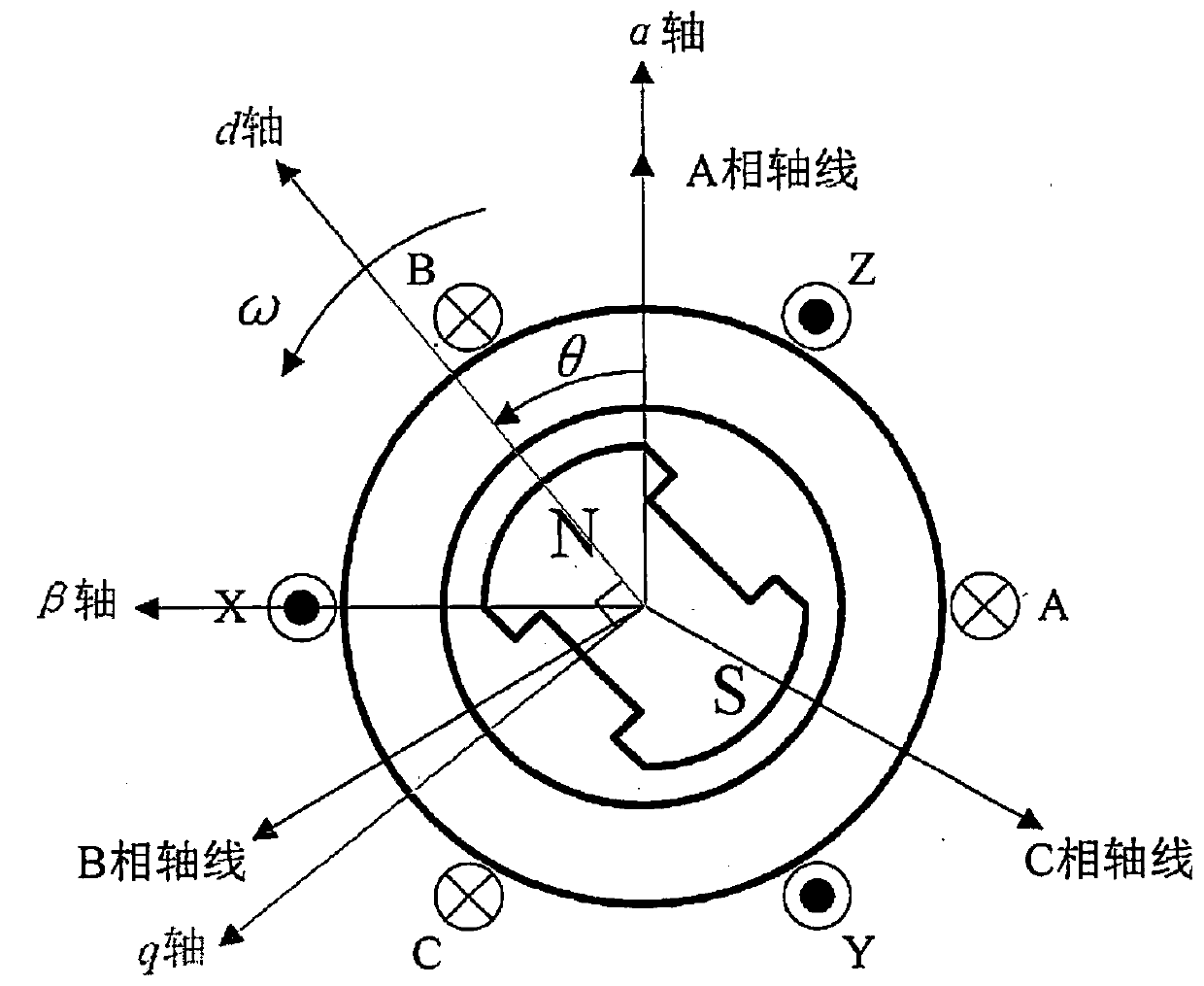
[0116] 3.1) Establish the three-phase coordinate system of the motor stator, where the axes of the motor stator windings are denoted as A, B and C respectively. There is an electrical angle difference of 120° between every two motor stator winding axes.

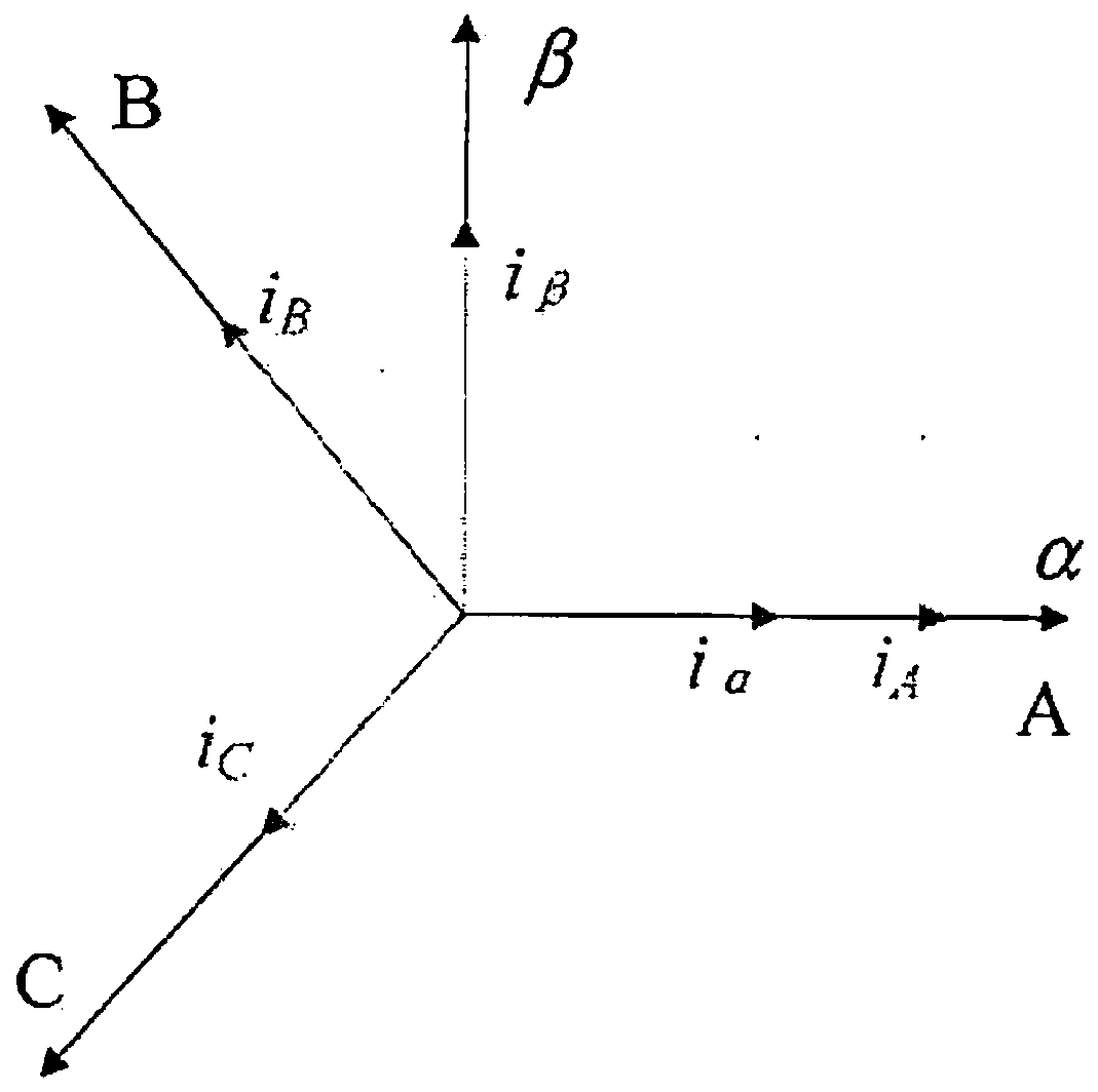
[0117] 3.2) Perform Clark transformation on the three-phase current in the three-phase coordinate system of the motor stator to obtain the two-phase current in the two-phase static coordinate system. Among them, the α-axis of the two-phase static coordinate system coincides with the A-axis of the three-phase coordinate system of the motor stator, and the β-axis leads the α-axis counterclockwise by 90° electrical angle.

[0118] The Clark transformation matrix and inverse transformation matri...


PUM


Abstract

The invention discloses an ultra-low-speed high-precision positioning control method of a frameless torque motor. The method mainly comprises the following steps: 1) adjusting the absolute position ofthe motor to zero; 2) calculating a mechanical angle theta<m> which should be rotated by the motor, an electrical angle theta<e> which should be rotated by the motor, a real-time position theta<1eal>of the motor and a real-time rotating speed omega<r> of the motor; 3) adjusting the angle of the rotor to theta<e>; 4) updating the exciting current i<d> according to the feedback rotating speed x<real> of the encoder and the rotating speed fluctuation requirement; and calculating the difference between the given reference value theta<tar> and the feedback value of the encoder to obtain a reference positioning offset, updating the reference value of the target position, and returning to the step 2 until the reference value of the target position is not updated any more. According to the invention, high torque can be maintained under the working condition of ultra-low-speed operation, and the anti-interference capability is excellent.

Description

technical field [0001] The invention relates to the field of motor control, in particular to an ultra-low-speed and high-precision positioning control method for a frameless torque motor. Background technique [0002] At present, there are several classic algorithms for the control of frameless torque motors: 1) vector control algorithm (FOC) with excitation component Id=0; 2) maximum torque current ratio control algorithm (MTPA); 3) direct torque Control algorithm (DTC); 4) Synovial film variable structure control; 5) Field weakening control algorithm; and some intelligent control algorithms: 6) Control algorithm based on nonlinear PID neural network; 7) Chaos control algorithm based on Hamilton model; 8 ) particle swarm optimization fuzzy PID control algorithm, etc. [0003] Problems with the above algorithms: Algorithm 1 has small self-disturbance rejection torque when running at ultra-low speed (below 0.2RPM), and there will be obvious torque ripple; Torque ripple at l...

Claims


Application Information

Patent Timeline
Patent Type & Authority Applications(China)
IPC IPC(8): H02P21/04H02P21/12H02P21/18H02P25/02H02P27/08
CPCH02P21/04H02P21/18H02P21/12H02P27/08H02P25/02Y02P70/10
Inventor 段黎明朱世涛王福全郑鑫
Owner CHONGQING UNIV
Why Eureka
Try Eureka