A Fault Diagnosis Method for Catenary Disconnector

A technology for isolating switch and fault diagnosis, which is applied in the direction of circuit breaker testing, instruments, measuring devices, etc., can solve the problems of no unified planning, single fault diagnosis of isolating switch, scattered fault diagnosis methods of isolating switch, etc., to achieve insulation Good performance, strong anti-electromagnetic interference ability, comprehensive diagnosis effect

Active Publication Date: 2022-04-26
EAST CHINA JIAOTONG UNIVERSITY
View PDF6 Cites 0 Cited by
  • Summary
  • Abstract
  • Description
  • Claims
  • Application Information

AI Technical Summary

Problems solved by technology

These commonly used isolating switch fault diagnosis methods are relatively scattered, and there is no unified planning together, which makes the diagnosis of isolating switch faults relatively simple, resulting in the staff being unable to accurately determine the type of isolating switch failure.

Method used


Image

  • A Fault Diagnosis Method for Catenary Disconnector
  • A Fault Diagnosis Method for Catenary Disconnector
  • A Fault Diagnosis Method for Catenary Disconnector

Examples


Embodiment Construction

[0040] The present invention will be described in further detail below in conjunction with the embodiments and with reference to the accompanying drawings.

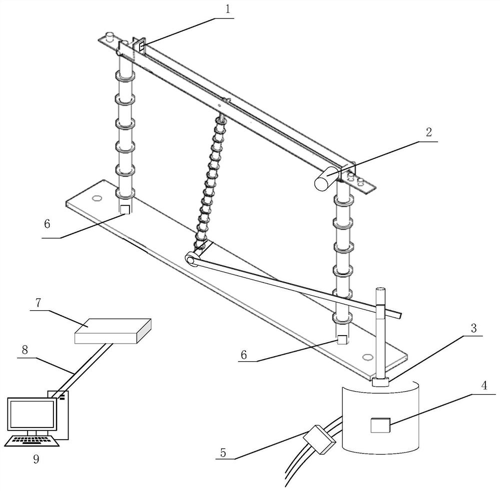
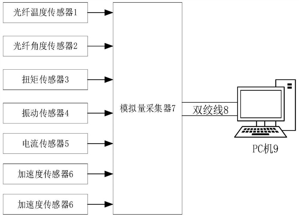
[0041] see Figure 1 to Figure 7 Shown is a catenary isolating switch fault diagnosis method in the present invention, which is applied to a diagnosis system, and the diagnosis system includes an optical fiber temperature sensor 1, an optical fiber angle sensor 2, a torque sensor 3, a vibration sensor 4, a current sensor 5, and an acceleration sensor 6. Analog quantity collector 7, twisted pair 8, PC 9.

[0042] Such as figure 1 As shown, the diagnostic system includes an optical fiber temperature sensor 1, an optical fiber angle sensor 2, a torque sensor 3, a vibration sensor 4, a current sensor 5, an acceleration sensor 6, an analog quantity collector 7, a twisted pair 8, a PC 9, an optical fiber temperature sensor The sensor 1 is installed on the moving contact of the catenary isolating switch to detect the temperatu...


PUM


Abstract

The present invention disclosed a method of exposure to the exposure network fault diagnosis method. It uses fiber temperature sensors, fiber angle sensors, torque sensors, vibration sensors, current sensors, and acceleration sensors.Transfer the collected values to the simulation collector for processing, the simulation collector then transmits the processed information to the PC through the twisted twisting line through the RS485 communication method, and establish a barrier -based neural network -based quarantine switch failure in the PCDiagnostic models only need to separate the contact network of different faulty types corresponding to the faulty characteristics of the contact network. Establish a fault diagnostic model in the neural network, can identify different types of faults, and display the final diagnosis results on the upper machine, which is convenient for staff to intuitively intuitivelyCheck the type of faulty existence in the corresponding isolation switch.

Description

technical field [0001] The invention relates to the field of fault diagnosis, in particular to a method for fault diagnosis of a catenary isolating switch. Background technique [0002] The isolating switch is the most widely used electrical equipment in substations, which can perform no-load switching operations on the circuit system to form an isolation disconnection point. The action is mainly completed by the electrical control part and the mechanical transmission part. However, due to the long-term exposure of the equipment to the outdoor environment, the corrosion and wear of the mechanism are relatively large, which accounts for a large proportion of the daily maintenance work of the substation. Most of the isolating switchgear in substations is an outdoor open structure, and the working environment is harsh, which leads to problems such as poor lubrication, rust jamming, and serious wear of various parts of the mechanical transmission part. Incomplete head contact w...

Claims


Application Information

Patent Timeline
Patent Type & Authority Patents(China)
IPC IPC(8): G01R31/327G01D21/02
CPCG01R31/3275G01D21/02
Inventor 胡军
Owner EAST CHINA JIAOTONG UNIVERSITY
Why Eureka
Try Eureka