
Safe data transmission circuit

A transmission circuit and data security technology, applied in the field of data security, can solve the problems of data transmission security error signal, difficulty in data security protection, signal transmission false alarm, etc.

Active Publication Date: 2020-05-19
STATE GRID HENAN INFORMATION & TELECOMM CO +1
View PDF13 Cites 2 Cited by
  • Summary
  • Abstract
  • Description
  • Claims
  • Application Information

AI Technical Summary

Problems solved by technology

[0002]The amount of data transmission is increasing more and more, resulting in continuous efforts to increase the amount of data transmission. On the basis of increasing the amount of data transmission, it is necessary to ensure data security. At the same time, as the amount of data transmission continues to increase, it is becoming more and more difficult to protect data security. At the same time, it is necessary to continuously upgrade and optimize data security transmission. The increase in data transmission volume is achieved through multi-channel synchronous transmission or increased bandwidth. For multi-channel synchronization Transmission requires synchronous detection of multiple channels at the same time. Different from traditional single-channel detection, it can play a security role. However, the current existing technology only performs security encryption detection on each channel on the basis of multi-channel transmission, and cannot To achieve synchronous multi-channel detection, it is easy to increase the time error between channels, resulting in data transmission security error signals, resulting in false alarms for signal transmission

Method used


Image

  • Safe data transmission circuit
  • Safe data transmission circuit
  • Safe data transmission circuit

Examples


Embodiment 1

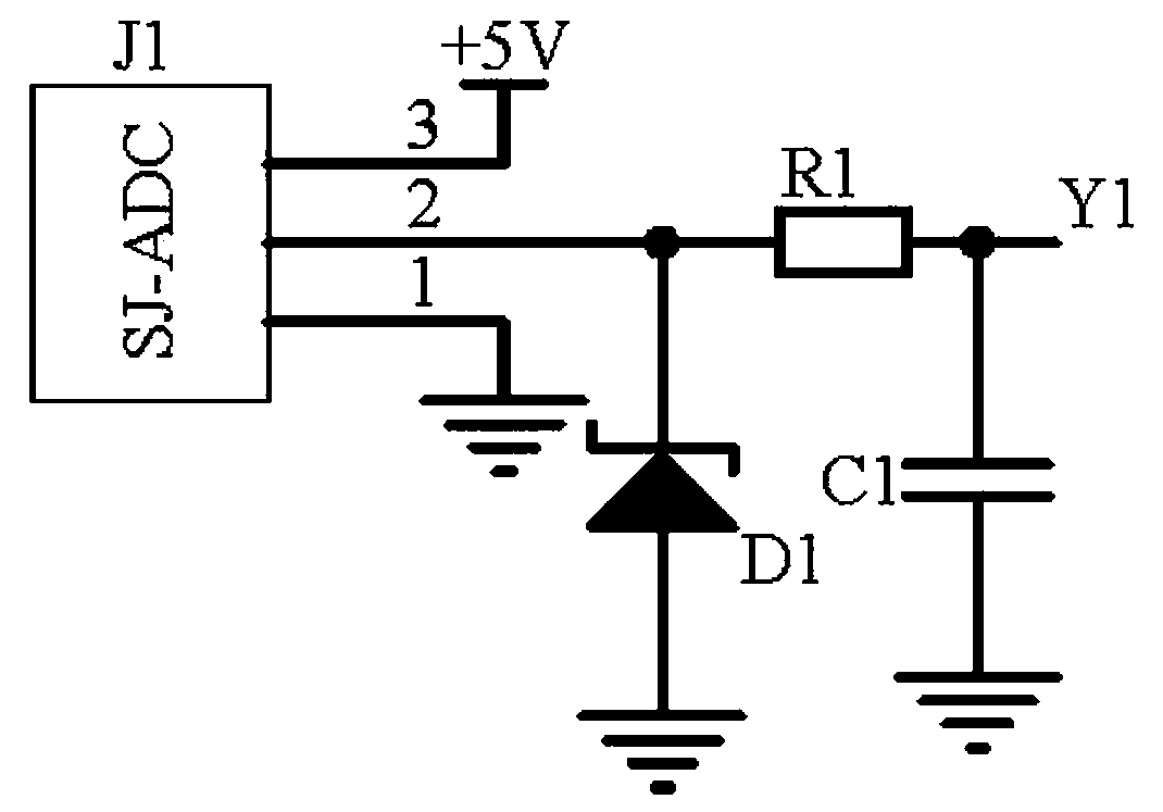
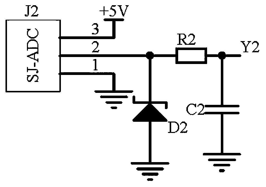
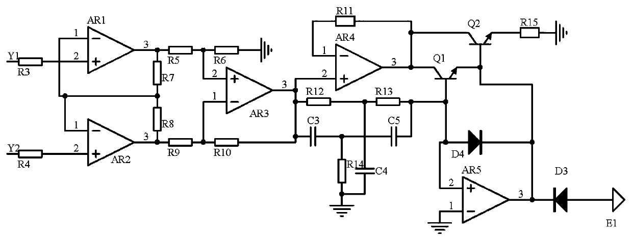
[0012] The first embodiment, a data security transmission circuit, including a frequency acquisition module 1, a frequency acquisition module 2, a differential adjustment module, the frequency acquisition module 1, the frequency acquisition module 2 uses the frequency collector J1 of the model SJ-ADC, the frequency The collector J2 collects the carrier signal frequency of the adjacent data channel. The differential adjustment module uses the operational amplifier AR1, the operational amplifier AR2, and the operational amplifier AR3 to form a differential operational amplifier circuit to output signals to the frequency acquisition module 1 and the frequency acquisition module 2. Differential-amplification adjustment. At the same time, the capacitor C3-capacitor C5 is used to form a frequency selection circuit to filter out the signal of a single frequency. At the same time, the transistor Q1 and the transistor Q2 are used to form a trimming circuit to detect and adjust the potenti...

Embodiment 2

[0015] The second embodiment, on the basis of the first embodiment, the frequency acquisition module 1, the frequency acquisition module 1, and the frequency acquisition module 2 use the frequency collector J1 and the frequency collector J2 of the model SJ-ADC to collect the carrier wave of the adjacent data channel For signal frequency, the power terminal of the frequency collector J1 is connected to the power supply +5V, the ground terminal of the frequency collector J1 is grounded, and the output terminal of the frequency collector J1 is connected to one end of the resistor R1 and the negative pole of the voltage regulator tube D1, and the positive pole of the voltage regulator tube D1 Ground, the other end of resistor R1 is connected to one end of capacitor C1 and the other end of resistor R3, the other end of capacitor C1 is grounded; the power terminal of frequency collector J2 is connected to the power supply +5V, the ground terminal of frequency collector J2 is grounded, ...


PUM


Abstract

The invention discloses a safe data transmission circuit, which comprises a frequency acquisition module 1, a frequency acquisition module 2 and a differential adjustment module, wherein the frequencyacquisition module 1 and the frequency acquisition module 2 use a frequency collector J1 and a frequency collector J2 of which the models are SJ-ADC to acquire carrier signal frequencies of adjacentdata channels; the differential adjustment module uses an operational amplifier AR1, an operational amplifier AR2 and an operational amplifier AR3 to form a differential operational amplifier circuitto perform differential-amplification adjustment on output signals of the frequency acquisition module 1 and the frequency acquisition module 2. Meanwhile, capacitors C3 to C5 are used for forming a frequency selection circuit to screen out a signal with a single frequency; meanwhile, a triode Q1 and a triode Q2 are used for forming a fine adjustment circuit to detect and adjust the potential of the signal; finally, an operational amplifier AR5, a diode D3 and a diode D4 are used for forming a peak value circuit to screen out a peak value signal to trigger a signal emitter E1 to work, the carrier signal frequency of adjacent data channels can be compared and adjusted, and the carrier signal frequency is converted into an error correction signal of a data control terminal.

Description

Technical field [0001] The invention relates to the technical field of data security, in particular to a data security transmission circuit. Background technique [0002] The increase in the amount of data transmission has led to continuous efforts to increase the amount of data transmission. On the basis of increasing the amount of data transmission, it is necessary to ensure data security. At the same time, as the amount of data transmission continues to increase, it is difficult to protect data security. It is becoming larger and larger, and it is necessary to continuously upgrade and optimize data security transmission at the same time. The increase of data transmission volume is through multi-channel synchronous transmission or increased bandwidth. For multi-channel synchronous transmission, it is necessary to simultaneously detect multiple channels at the same time, which is different from traditional single channels. Channel detection can play a security role, while the cu...

Claims


Application Information

Patent Timeline
IPC IPC(8): H03F3/45
CPCH03F3/45
Inventor 张勇舒新建刘岩李文萃秦晓阳安致嫄王慕维杨润华
Owner STATE GRID HENAN INFORMATION & TELECOMM CO
Learn More