Dual-rotor expander and using method thereof

An expander and double-rotor technology, which is applied in the field of expanders, fluid motors or pumps, and rotor-type fluid mechanical devices, can solve the problems of no volume expansion process in the expansion chamber, loss of energy transfer process, and inability to adjust the expansion ratio, etc., to achieve structural Simplicity, long service life and no wearing parts effect

Active Publication Date: 2020-05-22
崔有志
View PDF11 Cites 0 Cited by
  • Summary
  • Abstract
  • Description
  • Claims
  • Application Information

AI Technical Summary

Problems solved by technology

Application No. 201510195251.4 In the patent document named "Rotor Expander" (hereinafter referred to as Document 1), an expander with male and female rotor meshing is introduced. This machine has the advantages of simple structure and no axial force. The protruding blades of the rotor and the grooves of the female rotor need to be meshed and sealed, which requires high machining accuracy and surface roughness of the blades and groove surfaces, and surface finishing has always been a difficult point in processing; in order to seal, the top of the male rotor protruding blades To install a spring air seal, the small and precise air seal is difficult to process, and the top of the air seal rubs against the groove of the female rotor and the cylinder wall during operation, which is easy to be damaged; the expansion chamber has no closed volume expansion process, and the expansion ratio cannot be adjusted. The utilization rate of internal energy is low, and the efficiency is low; moreover, only the male rotor in the cylinder can act externally, and the female rotor only has the function of sealing, so the effective volume ratio is low
[0005] The application number is 201811031829.2 in the patent document titled "Spherical Ball Expander" (hereinafter referred to as Document 2), which introduces an inner and outer spherical expander. High-pressure gas pushes the ball to move and then drives the sphere to rotate; the sphere of this kind of expander is difficult to process. In addition, the gas expands to push the ball first, and the ball pushes the sphere, so there is a large loss in the energy transfer process

Method used


Image

  • Dual-rotor expander and using method thereof
  • Dual-rotor expander and using method thereof
  • Dual-rotor expander and using method thereof

Examples


Embodiment 1

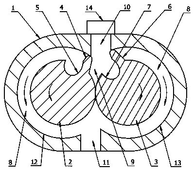
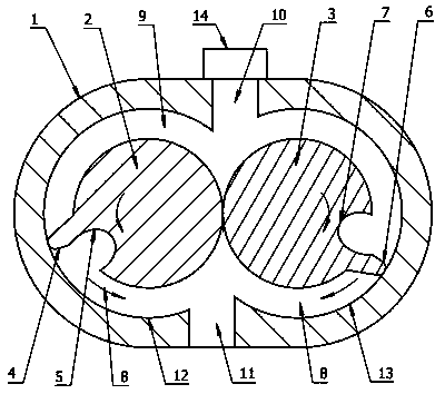
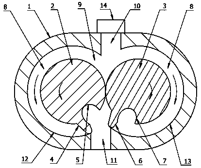
[0040] Such as figure 1 , figure 2 , image 3 , Figure 4 As shown, the present embodiment is a rotor expander, a fluid motor, a pump or a compressor, including a cylinder body 1, inside the cylinder body 1 there are two circular and partially overlapping rotor slots 12 and 13, the rotor slot 12 There are first rotor and second rotor respectively in the rotor groove 13, and there are gears driving the first rotor and the second rotor to rotate in opposite directions with a fixed speed ratio outside the cylinder body. Let me repeat. The main bodies of the first rotor and the second rotor are cylinders of equal thickness, and the outer circumferential surfaces are tangent, and the first rotor has protruding sealing teeth 4 extending radially outward from its outer circumference and radially inwardly recessed tooth grooves 5. The second rotor is provided with protruding sealing teeth 6 extending radially outward from its outer circumference and passing tooth grooves 7 recess...

Embodiment 2

[0047] Such as Figure 5 , Figure 6 As shown, the principle and structure of this embodiment and Embodiment 1 are basically the same, the difference is that this embodiment cancels the air intake control device 14, and sets the inlet 10 on the side of the second rotor, when the first rotor and the second rotor turn to Figure 5 In the position shown, the inlet 10 communicates with the slot 7 on the second rotor, and the high-pressure gas enters the expansion chamber 9 through the inlet 10 and the slot 7. When the inlet 10 is completely blocked by the side of the second rotor, the high-pressure gas no longer Enter the expansion chamber 9 to complete the intake process. Such as Figure 6 In the expansion stage shown, the high-pressure gas cools down in the expansion chamber 9 and performs work externally. The inlet 10 cooperates with the tooth groove 7 to control the amount of gas entering the expansion cavity 9, and replaces the intake control device 14, and adjusts the exp...

Embodiment 3

[0049] Such as Figure 7 , Figure 8 As shown, the principle and structure of this embodiment and Embodiment 1 are basically the same, the difference is that this embodiment cancels the air intake control device 14, opens a secondary air intake passage 21 on the first rotor, and opens a secondary inlet on the side of the rotor slot 12 16. Set the inlet 10 on the side of the second rotor, when the first rotor and the second rotor turn to Figure 7 In the position shown, the inlet 10 communicates with the tooth slot 7 on the second rotor, the auxiliary air intake channel 21 communicates with the auxiliary inlet 16, and the high-pressure gas enters the expansion chamber 9 through the inlet 10 and the auxiliary inlet 16. When the inlet 10 is completely filled by the second When the side of the second rotor is blocked and the auxiliary inlet 16 is completely blocked by the side of the first rotor, the high-pressure gas no longer enters the expansion chamber 9, and the intake proce...


PUM


Abstract

The invention discloses a dual-rotor expander. The dual-rotor expander comprises a cylinder body, two rotors with protruding blades and grooves are arranged in the cylinder body, the outer circumferential surfaces of the two rotors are tangent to each other, the blades and the grooves of the two rotors sequentially mesh with each other, the two rotors and the cylinder body form an expansion cavity, high-pressure fluid enters the expansion cavity from an inlet and then pushes the two rotor blades to rotate at a fixed speed ratio in opposite directions along respective rotating axes, and outputtorque does work outwards. The dual-rotor expander is simple in structure, easy to process, high in mechanical efficiency, high in effective volume rate, free of abrasion, long in service life and simple in maintenance.

Description

technical field [0001] The invention discloses a rotor type fluid mechanical device, which relates to the field of fluid machinery, in particular to an expander and fluid motor with high expansion efficiency, high effective volume ratio, easy processing, no wearing parts, long service life and low maintenance cost or pump. Background technique [0002] In recent years, with the development of my country's industry and people's living standards, more and more energy sources such as petroleum and coal are used, the greenhouse effect is becoming more and more serious, and the air quality is deteriorating. Energy conservation and emission reduction have become one of the national key tasks. There is a large amount of differential pressure energy in natural gas pipelines and urban natural gas pipeline networks. In heavy industrial enterprises such as chemical industry, steel, thermal power, and cement, there is a large amount of low-grade waste heat associated with the production...

Claims


Application Information

Patent Timeline
Patent Type & Authority Applications(China)
IPC IPC(8): F01C1/14F01C19/00F01C20/00F01C21/08F01C21/10F01C21/18
CPCF01C1/084F01C1/14F01C19/00F01C19/005F01C20/00F01C21/08F01C21/104F01C21/18F01C2021/12
Inventor 崔有志
Owner 崔有志
Why Eureka
Try Eureka