Machining process of showing stand

A processing technology and display rack technology, applied in the direction of coating, etc., can solve the problems of large surface grinding workload, lower product qualification rate, lower production efficiency, etc., achieve good protection effect, reduce the occurrence of defective products, and improve production efficiency effect

Inactive Publication Date: 2020-05-29
上海明勤金属制品有限公司
View PDF2 Cites 4 Cited by
  • Summary
  • Abstract
  • Description
  • Claims
  • Application Information

AI Technical Summary

Problems solved by technology

[0004] In the above application documents, the fixed angle of the display basket can be changed by installing the first support shaft in different positioning grooves to adapt to the display of different commodities. The surface is easily scratched during the process, which brings a large workload to the surface grinding work, resulting in a decrease in production efficiency, and when the iron plate and square tube are severely scratched, they can only be scrapped, which will also lead to qualified products. The efficiency has been reduced, and at the same time, repeated grinding will also bring about a large environmental pollution problem. Therefore, a new solution needs to be proposed to solve the above problems

Method used


Image

  • Machining process of showing stand
  • Machining process of showing stand
  • Machining process of showing stand

Examples


Embodiment 1

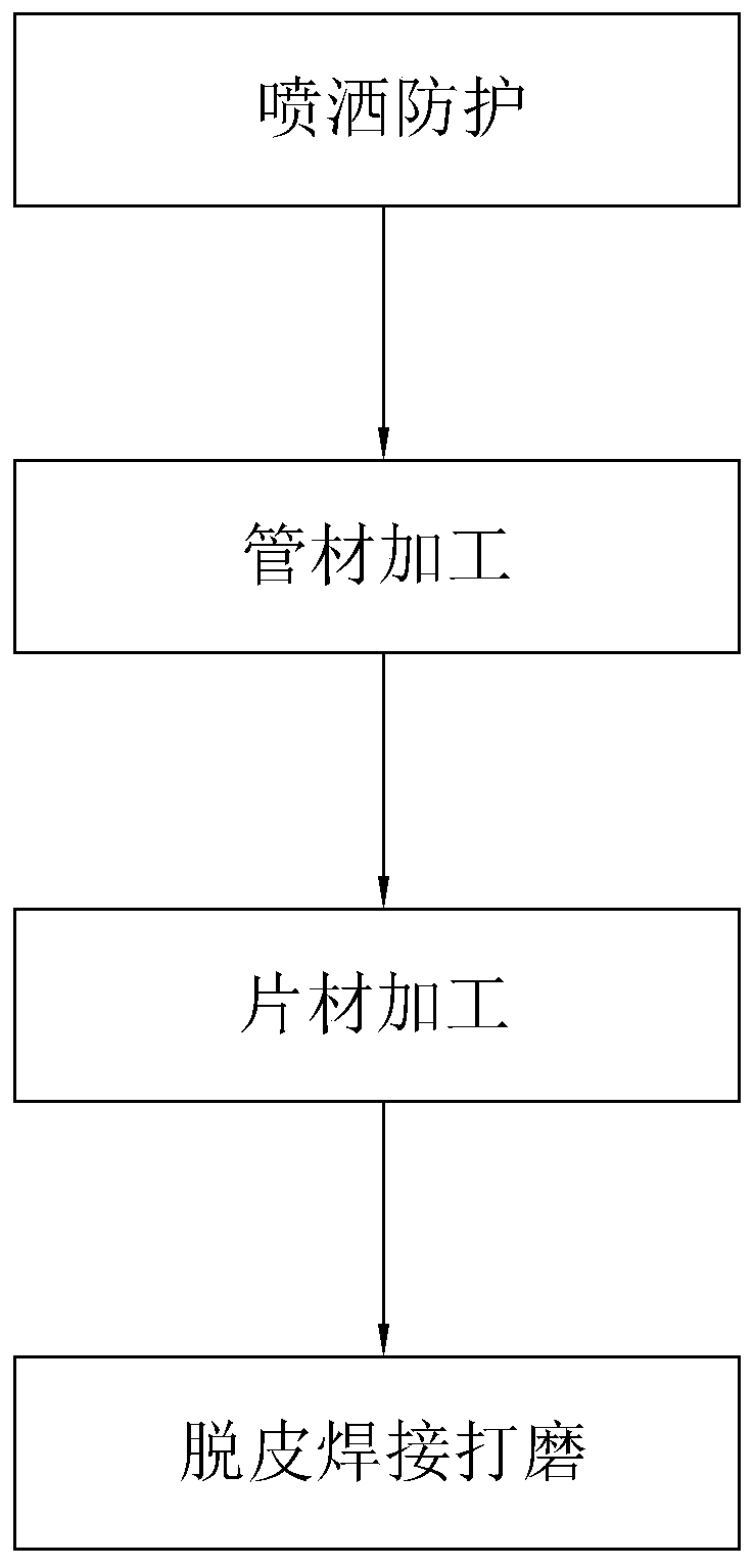
[0042] Embodiment 1: A processing technology of a display stand. The components of the protective liquid in step 1 and their corresponding parts by weight are shown in Table 1, and specifically include the following steps:

[0043] Step 1, spray protection, take the pipes and sheets used for processing and production, evenly spray protective liquid on the surface, and dry them to obtain the pretreated pipes and sheets;

[0044] Step 2, pipe processing, cutting, punching and bending the pretreated pipe according to the production drawings to obtain pipe fittings;

[0045]Step 3, sheet processing, cutting and bending the pretreated sheet according to the production drawings to obtain the sheet;

[0046] Step 4: Peeling, welding and grinding, peeling and cleaning the surface of the pipe fittings and pieces, then assembling them, and fixing them in the spot welding mold. After the automatic welding is completed, they are polished to obtain the display stand as shown in the product...

Embodiment 2-5

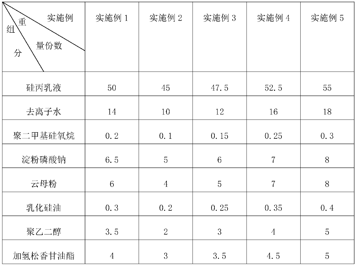
[0048] Embodiment 2-5: A processing technology of a display rack. The difference from Embodiment 1 is that the components of the protective liquid in Step 1 and their corresponding parts by weight are shown in Table 1.

[0049] Each component and parts by weight thereof in table 1 embodiment 1-5

[0050]

Embodiment 6

[0051] Embodiment 6: A processing technology of a display rack. The difference from Embodiment 1 is that the quality of polydimethylsiloxane in the protective liquid in step 1 is replaced by polyacrylic acid.


PUM

PropertyMeasurementUnit
Particle sizeaaaaaaaaaa

Abstract

The invention discloses a machining process of a showing stand, relates to the technical field of metal products, and solves the problem that the overall production efficiency and the percent of passof pipes and sheets are greatly reduced due to the fact that the surfaces of the pipes and the sheets are easily scratched in the machining process. The machining process of the showing stand comprises the following steps: step 1, spraying protection; step 2, pipe processing; step 3, sheet processing; and 4, peeling, welding and polishing. A protective liquid in the step 1 is prepared from the following components in parts by weight: 45-55 parts of silicone acrylic emulsion, 10-18 parts of deionized water, 0.1-0.3 parts of a leveling agent, 5-8 parts of a thickening agent, 4-8 parts of a wear-resistant filler, 0.2-0.4 parts of a defoaming agent, 2-5 parts of polyethylene glycol, and 3-5 parts of hydrogenated rosin glyceride. According to the machining process of the showing stand, the surfaces of the pipes and the sheets are not prone to being scratched in the application process, and therefore high production efficiency and high percent of pass are achieved.

Description

technical field [0001] The invention relates to the technical field of metal product processing, more specifically, it relates to a processing technology of a display stand. Background technique [0002] Display racks are also known as product display racks, promotional racks, portable exhibits and data racks, etc., which are mainly used in electronics (IT), decoration, tobacco and wine, supplies display, women's products, boutiques, crystal crafts class, crystal glue products, etc. [0003] In the Chinese invention patent application document with the publication number CN108158298A, a commodity display stand and its production process are disclosed. The base and the support frame vertically connected to the base, each of the display baskets is connected to the support frame through a connection assembly, the connection assembly includes connecting arms arranged on both sides of the display basket and a positioning piece connected to the support frame, The first support s...

Claims


Application Information

Patent Timeline
IPC IPC(8): C09D133/04C09D7/65
CPCC08L2205/035C09D143/04C09D7/65C08L71/02C08L93/04
Inventor 刘富强孔凡龙朱素连范峰
Owner 上海明勤金属制品有限公司
Why Eureka
Try Eureka