
Waste incineration waste heat boiler system with flue gas reheating function

A technology for waste incineration and waste heat boilers, which is applied to boiler water pipes, steam boilers, steam boiler accessories, etc. It can solve the problems of increased corrosion risk of high-temperature heating surfaces, achieve reasonable utilization of heat energy, shorten length, and avoid high-temperature corrosion effects

Pending Publication Date: 2020-05-29
SHANGHAI BOILER WORKS
View PDF0 Cites 2 Cited by
  • Summary
  • Abstract
  • Description
  • Claims
  • Application Information

AI Technical Summary

Problems solved by technology

[0004] The selection of the main steam temperature is mainly limited by the increase of the temperature, which directly causes the corrosion risk of the high temperature heating surface to increase

Method used


Image

  • Waste incineration waste heat boiler system with flue gas reheating function

Examples


Embodiment Construction

[0021] Below in conjunction with specific embodiment, further illustrate the present invention. It should be understood that these examples are only used to illustrate the present invention and are not intended to limit the scope of the present invention. In addition, it should be understood that after reading the teachings of the present invention, those skilled in the art can make various changes or modifications to the present invention, and these equivalent forms also fall within the scope defined by the appended claims of the present application.

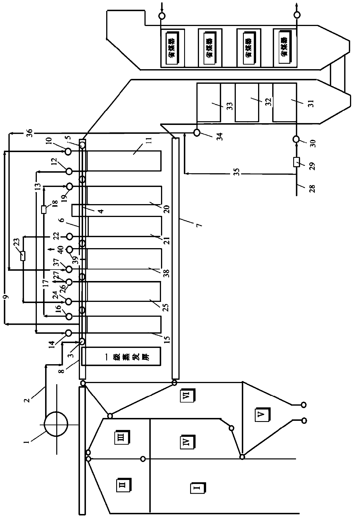
[0022] Such as figure 1 As shown, the waste incineration waste heat boiler disclosed in this embodiment adopts ∏ layout as a whole. It should be noted that the technical solution disclosed in this application is not only applicable to waste incineration waste heat boilers with ∏ layout, but also suitable for waste incineration in other arrangements. Waste heat boiler. Although this embodiment takes the Π-type arrangement as a...


PUM


Abstract

The invention relates to a waste incineration waste heat boiler system with a flue gas reheating function. The waste incineration waste heat boiler system is characterized in that the waste incineration waste heat boiler system comprises a first flue to an N flue sequentially arranged in the flue gas flowing direction, the Nflue is a horizontal flue defined by superheaters in a surroundingmode, and a water-cooled evaporation screen, the first-level second superheater, the third-level superheater, a second-level reheater, the second-level second superheater, the second-level first superheater and the first-level first superheater are sequentially arranged in the horizontal flue; and the N flue communicates with a tail front flue, the tail front flue is connected with a tail rear flue in series, the tail front flue and the tail rear flue are composed of surrounding plates, and a first-level reheater and an economizer are arranged in the tail front flue and the tail rear fluecorrespondingly. The fume temperature in the area where a first-level reheater is located is low, and the first-level reheater is arranged in the tail flue composed of the surrounding plates, so thatcompared with the scheme that all convection heating surfaces are arranged in the horizontal flue, the floor space can be saved.

Description

technical field [0001] The invention relates to a garbage incineration waste heat boiler system. Background technique [0002] Garbage fuel fluctuates greatly, and the combustion process, flue gas composition, flue gas volume and flue temperature fluctuate greatly; the composition of incinerator flue gas is complex, including chlorides, alkali metals and heavy metals, etc.; the content of solid substances with low melting points in flue gas dust is high. The steam parameters of existing waste incinerators are kept relatively low due to the high concentration of chemical elements and high temperature, which makes the tube bundles on the hot side easy to corrode. [0003] Due to the complex flue gas atmosphere in the water wall area, the temperature of the outer wall of the pipe on the fire side is higher in the area with higher smoke temperature, the pressure of the main steam increases, the pressure of the steam drum and the water wall increases accordingly, and the correspo...

Claims


Application Information

Patent Timeline
IPC IPC(8): F22B1/18F23J15/06F22B37/10F22G7/12F22G5/00
CPCF22B1/18F22B37/107F22G5/00F22G7/12F23J15/06Y02E20/30
Inventor 辛少杰郭琴琴徐雪元董师宏袁玉洁
Owner SHANGHAI BOILER WORKS
Learn More