Assembled fireproof experimental furnace and fireproof experimental system containing same
A refractory experiment and assembly technology, applied in the direction of furnace, furnace lining, furnace cooling, etc., can solve the problems of immature assembly research of the overall experimental furnace and its supporting facilities, failure to meet the experimental requirements, waste of manpower and time, etc., to reduce assembly Difficulty, ease of assembly, cost-saving effect
- Summary
- Abstract
- Description
- Claims
- Application Information
AI Technical Summary
Problems solved by technology
Method used
Image

Examples
Embodiment 1
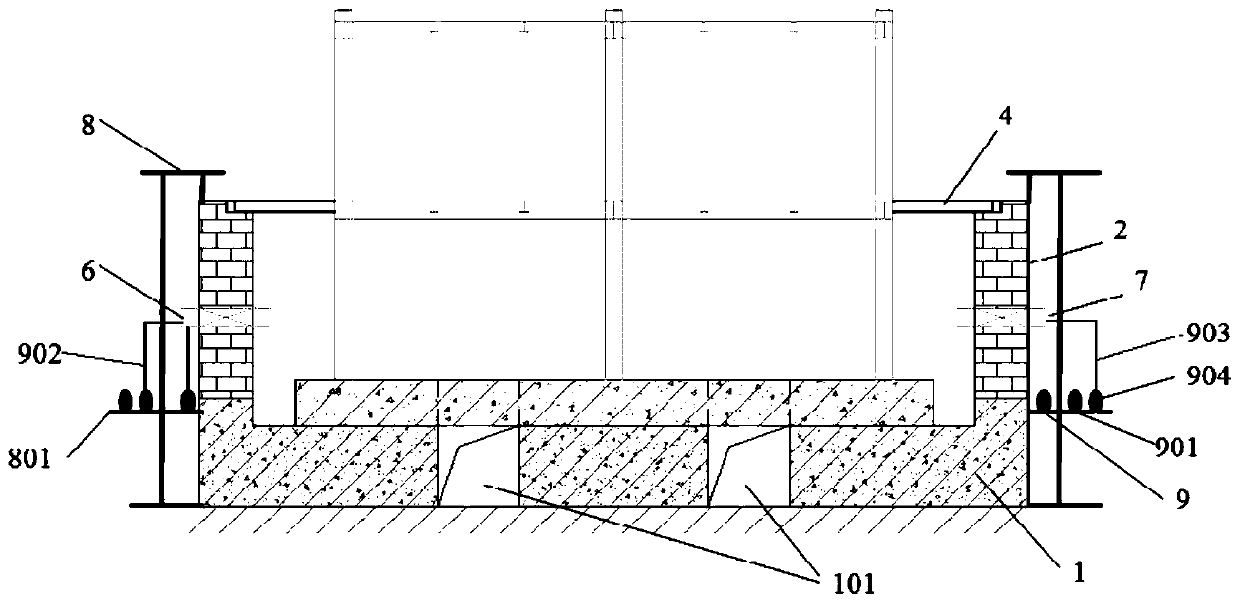
[0048] Example 1 Horizontal horizontal refractory experimental furnace
[0049] The structure of the horizontal horizontal assembly type refractory experimental furnace of the present embodiment is as follows: Figure 1-3 As shown, the refractory experimental furnace includes a base 1 , a furnace body 2 , a steel frame structure, a burner 6 and a high-temperature camera 7 . The base 1 is arranged below the furnace body 2 to support and insulate the furnace body 2, while leaving a space between the furnace body 2 and the ground to facilitate the arrangement of the first row of flues 101 below the furnace body 2. The base 1 and the furnace body 2 are connected as a whole through high-temperature-resistant cotton, so as to improve the buffering, sealing and thermal insulation properties of the refractory experimental furnace. The burner 6 and the high-temperature camera 7 enter the furnace through the reserved holes on the special-shaped plate of the ceramic fiber zirconium shie...
Embodiment 2
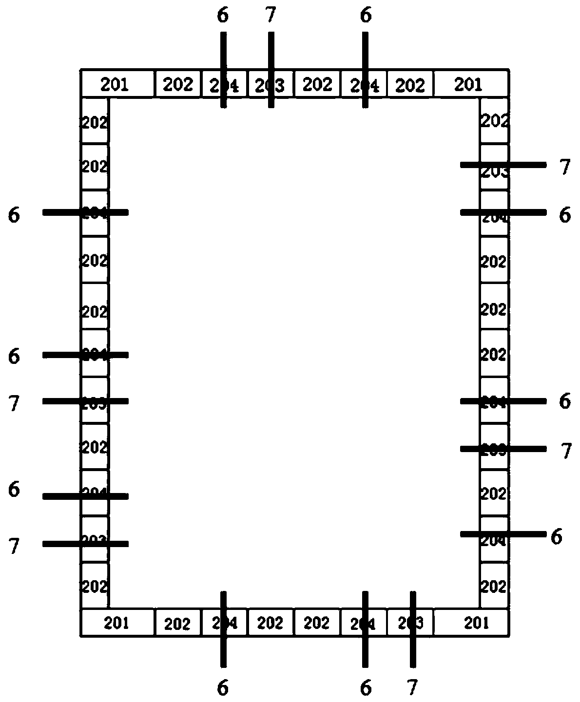
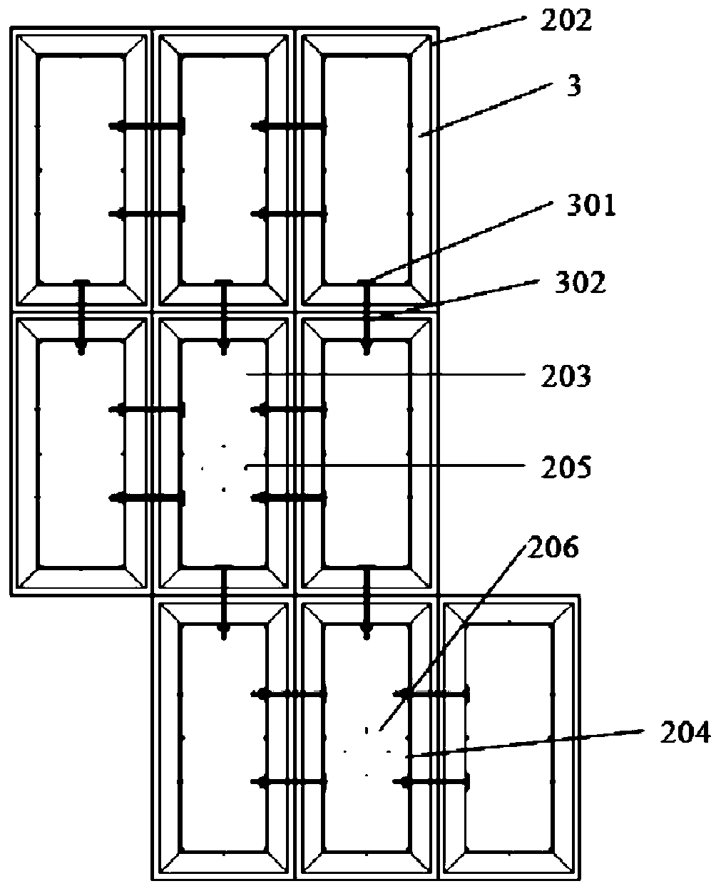
[0062] Embodiment 2 vertical vertical refractory experimental furnace
[0063] The structure of the vertical assembled refractory experimental furnace of this embodiment is as follows: Figure 4 As shown, the shape of the body of furnace 2 is a vertical cube. The bottom layer of the furnace body 2 is assembled by 12 ceramic fiber zirconium shield special-shaped plates. When not in use, the special-shaped plates are disassembled and occupy a small area. The bottom layer of the furnace body 2 includes two first special-shaped plates 201 , four second special-shaped plates 202 , two third special-shaped plates 203 and four fourth special-shaped plates 204 . The first special-shaped plates 201 are arranged at two corner positions of the furnace body 2 . The furnace body 2 is assembled from three layers of ceramic fiber zirconium shield special-shaped plates in height. The fourth special-shaped plate 204 and the supporting six burners 6 are evenly arranged on both sides of the f...
Embodiment 3
[0067] Embodiment 3 Fire resistance experiment system
[0068] The structure of the fire resistance experiment system of the present embodiment is as follows: Figure 5 As shown, the fire-resistant experimental system includes the fire-resistant experimental furnace of embodiment 1, smoke exhaust system, gas supply device, oil supply device and control system, and the smoke exhaust system includes a smoke collection hood 10 and a smoke exhaust fan 11, and the smoke collection hood 10 is located at Above the refractory experimental furnace, the exhaust fan 11 is connected in parallel with the second flue 1001 and the first flue 101 of the fume collecting hood through the exhaust pipe; the gas supply device is connected to the cooling gas pipeline 904, and the oil supply device is connected to the oil supply pipeline The control system is connected to the burner 6, exhaust fan 11, gas supply device and oil supply device to control the combustion and smoke exhaust conditions of t...
PUM
| Property | Measurement | Unit |
|---|---|---|
| thickness | aaaaa | aaaaa |
| density | aaaaa | aaaaa |
| density | aaaaa | aaaaa |
Abstract
Description
Claims
Application Information
 - R&D
- Intellectual Property
- Life Sciences
- Materials
- Tech Scout
- Unparalleled Data Quality
- Higher Quality Content
- 60% Fewer Hallucinations
Browse by: Latest US Patents, China's latest patents, Technical Efficacy Thesaurus, Application Domain, Technology Topic, Popular Technical Reports.
© 2025 PatSnap. All rights reserved.Legal|Privacy policy|Modern Slavery Act Transparency Statement|Sitemap|About US| Contact US: help@patsnap.com